Eureka AIR delivers breakthrough ideas for toughest innovation challenges, trusted by R&D personnel around the world.

Sound amplifying horn of loudspeaker

A loudspeaker and horn technology, applied in the field of loudspeakers, can solve the problems of easy vibration, simple structure, inability to adjust, etc., and achieve the effects of easy operation, improved support, and strong adaptability

Pending Publication Date: 2021-04-30
宁波向阳坦科斯特电子有限公司
View PDF0 Cites 0 Cited by
  • Summary
  • Abstract
  • Description
  • Claims
  • Application Information

AI Technical Summary

Problems solved by technology

[0004] The purpose of the present invention is to provide a loudspeaker horn to solve the problem that the loudspeaker horns of the prior art proposed in the background art are mostly single-channel funnel-shaped, simple in structure, unable to adjust, poor in stability, and prone to jitter The problem

Method used


Image

  • Sound amplifying horn of loudspeaker
  • Sound amplifying horn of loudspeaker
  • Sound amplifying horn of loudspeaker

Examples


Embodiment Construction

[0019] The following will clearly and completely describe the technical solutions in the embodiments of the present invention with reference to the accompanying drawings in the embodiments of the present invention. Obviously, the described embodiments are only some, not all, embodiments of the present invention.

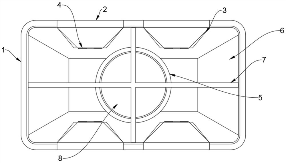
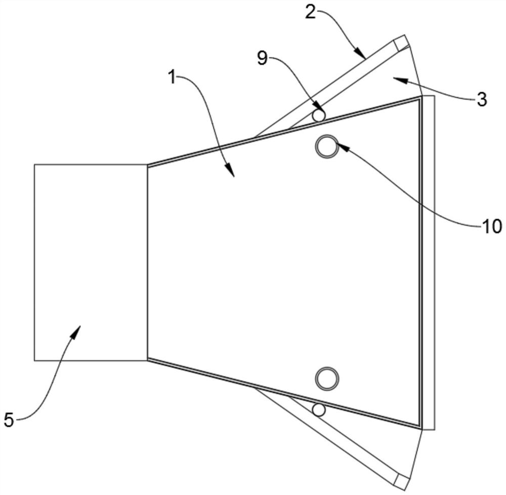
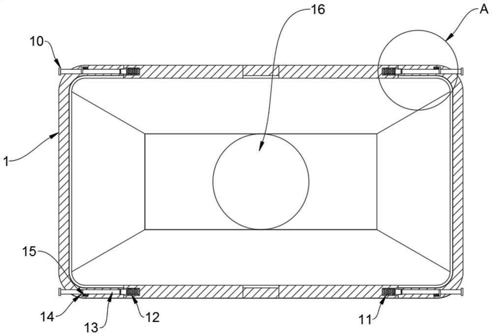
[0020] see Figure 1-4 , an embodiment provided by the present invention: a loudspeaker horn, comprising a horn shell 1, the upper end and the lower end of the horn shell 1 are equipped with a sound board 2, the sound board 2 is provided with four A connecting hinge 4 is arranged between the four sounding boards 2 and the sounding horn shell 1, the sounding board 2 is movably connected with the sounding horn shell 1 through the connecting hinges 4, and a loudspeaker body 5 is installed inside the sounding horn shell 1 The front end of the loudspeaker main body 5 is provided with a partition rib 7, and both sides of the partition rib 7 are provided with a sound reinfo...


PUM


Abstract

The invention discloses a sound amplifying horn of a loudspeaker, relates to the field of loudspeakers, and aims to solve the problems that most loudspeaker horns in the prior art are arranged in a single-channel funnel shape, are simple in structure, cannot be adjusted, are poor in stability and are liable to shake. The sound amplifying horn comprises a sound amplifying horn shell, wherein four sound amplifying plates are installed at the upper end and the lower end of the sound amplifying horn shell respectively, connecting hinges are arranged between the four sound amplifying plates and the sound amplifying horn shell, the sound amplifying plates are movably connected with the sound amplifying horn shell through the connecting hinges, a loudspeaker main body is installed in the sound amplifying horn shell, a separation rib is installed on the front end face of the loudspeaker body, sound amplifying cavities are formed in the two sides of the separation rib, a supporting column is installed on one side of the sound amplifying plate, connecting rods are installed on the two sides of the interior of the sound amplifying horn shell, and sound receiving cloth is arranged between the sound amplifying horn shell and the sound amplifying plate.

Description

technical field [0001] The invention relates to the technical field of loudspeakers, in particular to a loudspeaker horn. Background technique [0002] The horn speaker originated from the phonograph. In 1928, Wente and Thuras produced their high efficiency horn speaker receiver. The principle of the horn speaker is that the diaphragm pushes the air at the bottom of the horn to work. Because of the large sound resistance, the efficiency is very high, but because the shape and length of the horn will affect the tone, it is not easy to reproduce low frequencies. Today, high-efficiency horn loudspeakers are mainly used in the field of professional sound reinforcement. The vibration system of the horn speaker is similar to that of the paper cone speaker, except that its diaphragm is not a paper cone, but a dome-shaped diaphragm. The vibration of the diaphragm radiates sound waves into the air through the horn (after two reflections). It has a large volume and is often used f...

Claims


Application Information

Patent Timeline
Patent Type & Authority Applications(China)
IPC IPC(8): H04R1/02H04R27/04
CPCH04R1/02H04R27/04
Inventor 高建华
Owner 宁波向阳坦科斯特电子有限公司
Why Eureka
Eureka Blog
Learn More