High-cleanness wet process equipment suitable for acid supply system
A kind of equipment and acid supply technology, which is applied in the direction of electrical components, semiconductor/solid-state device manufacturing, circuits, etc., can solve the problem of low cleaning efficiency of single-chip cleaning equipment, inability to effectively guarantee the quality of wafers, and the inability of chemical cleaning fluid to be cleaned in sections, etc. question
- Summary
- Abstract
- Description
- Claims
- Application Information
AI Technical Summary
Problems solved by technology
Method used
Image
Examples
Embodiment 1
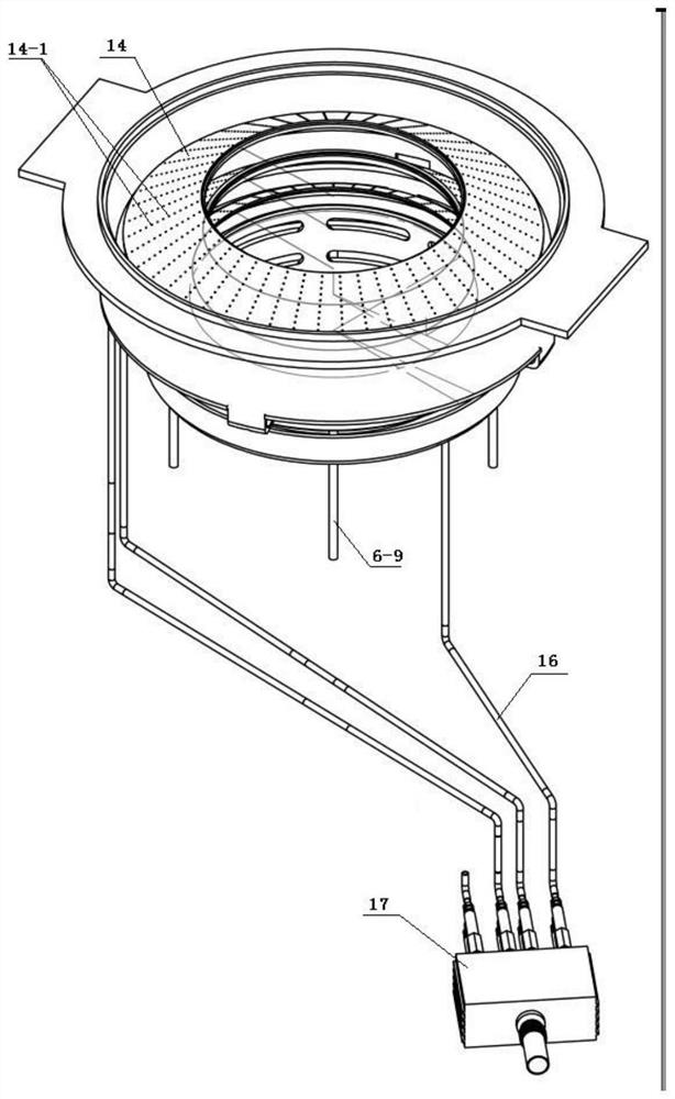
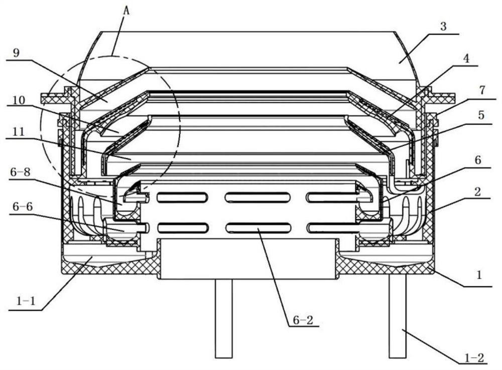
[0148] Embodiment 1, the composite cavity structure of the single-chip wafer cleaning equipment given in this embodiment includes a cavity shell 1, a support ring 2, a first isolation component and a second isolation component, and the first isolation component is installed There are jacking elements 8.
[0149] Wherein, the first isolation assembly includes a first-layer isolation ring 3 and a third-layer isolation ring 5 , and the second isolation assembly includes a second-layer isolation ring 4 and a fourth-layer isolation ring 6 .
[0150] The first layer of isolation ring 3 includes a first ring body 3-1, and a first isolation cover 3-2 extending from the inner wall of the first ring body 3-1 gradually slopes upward from the outside to the inside. A first ring edge 3-3 extends horizontally from the outer wall of the ring body 3-1, and a first locking groove 3-4 is opened at the bottom of the first ring edge 3-3.
[0151] The second layer isolation ring 4 includes a seco...
Embodiment 2
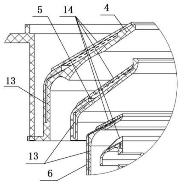
[0219] Embodiment 2. The structure of the high-clean wafer wet cleaning device given in this embodiment is basically the same as that of Embodiment 1. The specific difference is that the second layer of the composite cavity structure of the wafer cleaning equipment in this embodiment Conduit grooves 13 are also provided inside the isolation ring 4 , the third layer isolation ring 5 and the fourth layer isolation ring 6 .
[0220] The catheter groove on the second layer of isolation ring 4 communicates with the first layer of drainage cavity 9, the catheter groove on the third layer of isolation ring 5 communicates with the second layer of drainage cavity 10, and the fourth layer of isolation ring 6 The catheter groove communicates with the drainage cavity 11 of the third layer.
[0221] The conduit groove on the second-layer isolation ring 4 is arranged in its second ring body 4-1.
[0222] The conduit groove on the third layer of isolation ring 5 is arranged in its third iso...
Embodiment 3
[0234] Embodiment 3, the structure of the composite chamber used for wafer cleaning equipment given in this embodiment is basically the same as Embodiment 1 or Embodiment 2, the specific difference is that the first layer of isolation ring 3, the second The lower surfaces of the layer isolation ring 4 , the third layer isolation ring 5 and the fourth layer isolation ring 6 are respectively provided with splash guards 15 .
[0235] In this embodiment, other specific implementation manners are the same as those in Embodiment 1 or Embodiment 2, and details are not repeated here.
PUM
 Abstract
Description
Claims
Application Information
 - R&D Engineer
- R&D Manager
- IP Professional
- Industry Leading Data Capabilities
- Powerful AI technology
- Patent DNA Extraction
Browse by: Latest US Patents, China's latest patents, Technical Efficacy Thesaurus, Application Domain, Technology Topic, Popular Technical Reports.
© 2024 PatSnap. All rights reserved.Legal|Privacy policy|Modern Slavery Act Transparency Statement|Sitemap|About US| Contact US: help@patsnap.com


