Packaging box grinding and polishing device
A technology of polishing device and packaging box, which is applied in the direction of grinding/polishing equipment, grinding machines, abrasive belt grinding machines, etc., which can solve problems such as low efficiency and uneven quality, and achieve good results, uniform quality, and improved work efficiency.
- Summary
- Abstract
- Description
- Claims
- Application Information
AI Technical Summary
Problems solved by technology
Method used
Image
Examples
Embodiment 1
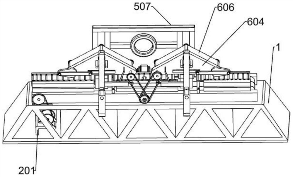
[0034] Specific implementation methods, such as Figure 1-11As shown, it includes a bottom frame 1, an automatic feeding device, a limit toggle mechanism, an automatic turning mechanism, an automatic clamping device, and an automatic grinding and polishing device. The components are fixedly connected to the upper part of the bottom frame 1, some components of the limit toggle mechanism are fixedly connected to the automatic feeding device, the automatic turning mechanism is set at the groove of the bottom frame 1, and some components of the automatic turning mechanism are fixedly connected to the bottom frame 1. Some components of the automatic clamping device are fixedly connected to the chassis 1, some components of the automatic grinding and polishing device are fixedly connected to the automatic clamping device, and the automatic grinding and polishing devices are symmetrically distributed around the center of the automatic turning mechanism.
[0035] Before preparing the ...
Embodiment 2
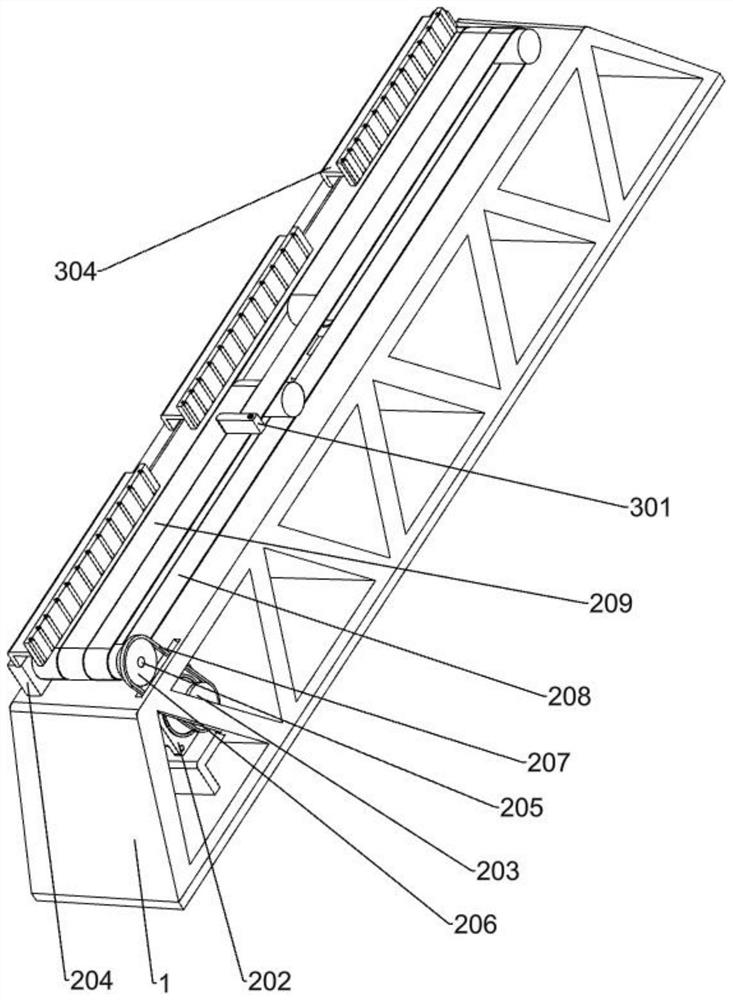
[0037] When used, such as figure 2 As shown, the automatic feeding device has a motor fixing plate 201, a first motor 202, a first synchronous wheel 203, a strip baffle 204, a first carrier roller 205, a second synchronous wheel 206, a first belt 207, and a second belt 208 and the third belt 209, the motor fixing plate 201 is fixedly connected to the inside of the left side of the chassis 1, the first motor 202 is fixedly connected to the top of the motor fixing plate 201, and the first synchronous wheel 203 is fixedly connected to the front end of the output shaft of the first motor 202. The inner walls of the side long baffles 204 are provided with guide grooves, the long baffles 204 on both sides are fixedly connected to the upper part of the chassis 1, and the first roller 205 is rotatably connected to both sides of the long baffles 204 and the bottom frame 1. On the left and right sides of the groove, the second synchronous wheel 206 is fixedly connected to the front end...
Embodiment 3
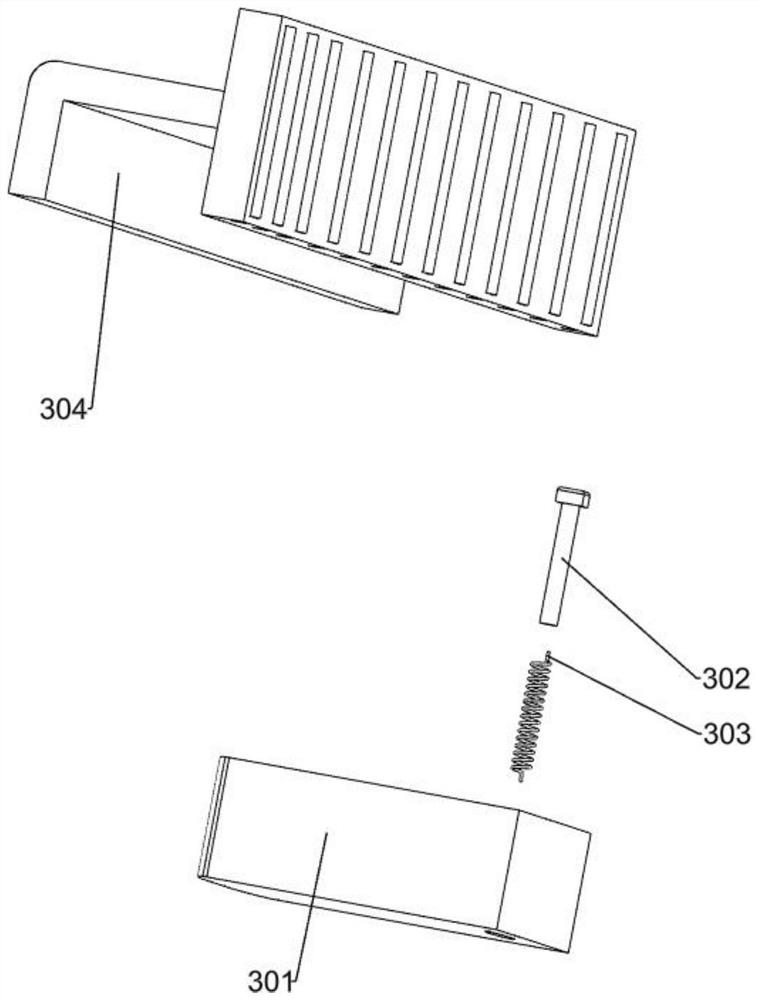
[0040] When used, such as image 3 As shown, the limit toggle mechanism has a rotating block 301, a pin 302, a torsion spring 303 and a limit plate 304. The rotating block 301 is rotatably connected to the front side strip baffle 204, and the rear side of the rotating block 301 has a groove. The pin 302 is embedded in the groove of the rotating block 301, the lower end of the torsion spring 303 is fixedly connected in the rotating block 301, the upper end of the torsion spring 303 is fixedly connected on the pin 302, and the upper part of the strip baffle plate 204 on both sides is evenly distributed and fixedly connected with three limits. Position plates 304, each limit plate 304 is provided with a plurality of small rollers.
[0041] By setting the pin 302 and the torsion spring 303 on the rotating block 301, the wooden box transported on the automatic feeding device can be moved, and the limit plate 304 is fixedly connected to the long strip baffles 204 on both sides to li...
PUM
 Abstract
Description
Claims
Application Information
 - R&D Engineer
- R&D Manager
- IP Professional
- Industry Leading Data Capabilities
- Powerful AI technology
- Patent DNA Extraction
Browse by: Latest US Patents, China's latest patents, Technical Efficacy Thesaurus, Application Domain, Technology Topic, Popular Technical Reports.
© 2024 PatSnap. All rights reserved.Legal|Privacy policy|Modern Slavery Act Transparency Statement|Sitemap|About US| Contact US: help@patsnap.com


