Dissolving zone nitrate water automatic blending system

A technology for dissolving and nitrifying water, applied in the directions of dissolving, mixer accessories, mixers, etc., can solve the problems of low degree of automation, low efficiency of nitric water dispensing in the dissolving area, etc., and achieve the effect of preventing spillage

Pending Publication Date: 2021-04-30
四川省洪雅青衣江元明粉有限公司
View PDF0 Cites 0 Cited by
  • Summary
  • Abstract
  • Description
  • Claims
  • Application Information

AI Technical Summary

Problems solved by technology

[0003] The purpose of the present invention is to provide an automatic deployment system of nitric water in the melting zone, which solves the problems of low automation and low efficiency of nitric water deployment in the existing melting zone

Method used


Image

  • Dissolving zone nitrate water automatic blending system

Examples


Embodiment 1

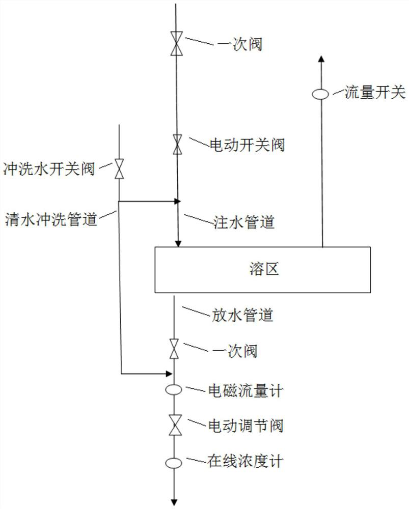
[0029] An automatic dispensing system for nitrate water in the melting zone, including a water injection pipeline connected to the water inlet of the melting zone, an electric on-off valve is installed on the water injection pipeline, a flow switch is installed at the emptying port of the melting zone, and a water discharge port of the melting zone is also connected with a The water discharge pipeline is equipped with an electromagnetic flowmeter, an electric control valve, and an online concentration meter in sequence, and a PLC control system is installed on the water discharge pipeline. The electric switch valve, flow switch, electromagnetic flowmeter, electric control valve, and online concentration meter are all connected to the PLC control system signal connection.

[0030]Through this setting, when performing water injection control in the melting zone, the PLC control system starts the electric on-off valve, and the water injection pipe injects water into the melting zo...

Embodiment 2

[0032] On the basis of Embodiment 1, both the water injection pipeline and the water discharge pipeline are connected with clean water flushing pipelines, and the clean water flushing pipeline is equipped with a flushing water switching valve, and the flushing water switching valve is connected to the PLC control system signal. Through this setting, the PLC control system activates the flushing water on-off valve on the clean water flushing pipeline, so that the water injection pipeline, water discharge pipeline, electric on-off valve, electromagnetic flowmeter, electric regulating valve, and online concentration meter in the melting zone are cleaned, and the nitric acid in the pipeline is eliminated. The water crystallizes, so that the equipment can reach the most ideal working state, and the normal operation of the deployment system will not be affected by the crystallization of nitrate water.

Embodiment 3

[0034] On the basis of the above embodiments, a primary valve is installed on the water injection pipeline at the front end of the electric on-off valve. With this arrangement, the water injection pipe can be prevented from leaking and clogging.


PUM


Abstract

The invention discloses a dissolving zone nitrate water automatic blending system, belongs to the technical field of dissolving zone nitrate water blending, aims to provide the dissolving zone nitrate water automatic blending system, and solves the problems of low dissolving zone nitrate water blending automation degree and low dissolving zone nitrate water blending efficiency in the prior art. The system comprises a water injection pipeline communicated with a water inlet of a dissolving area, an electric switch valve is installed on the water injection pipeline, a flow switch is further installed at an emptying port of the dissolving area, a water discharging port of the dissolving area is further communicated with a water discharging pipeline, and an electromagnetic flowmeter, an electric adjusting valve, an online concentration meter and a PLC control system are sequentially installed on the water discharging pipeline. The electric switch valve, the flow switch, the electromagnetic flowmeter, the electric regulating valve and the online concentration meter are all in signal connection with the PLC control system. The dissolving zone nitrate water automatic blending system is suitable for the automatic blending system of the dissolved zone nitrate water.

Description

technical field [0001] The invention belongs to the technical field of dissolving nitric water preparation, and in particular relates to an automatic dispensing system of dissolving nitric water. Background technique [0002] The current deployment of raw nitrate in the mine, from opening and closing gate valves to controlling the water volume of each gate valve, is completely manual operation. Due to the high repetitiveness and high work intensity of the operators, they are prone to lack of work responsibility, which in turn leads to untimely deployment of nitric water and very low efficiency of nitric water deployment. With the development of society, there is a shortage of labor force, and the leanness of production requirements is getting higher and higher. Manual deployment of nitrate water is increasingly unable to meet the current production needs. Therefore, it is of great significance to develop an automatic deployment system of nitrate water in the melting zone. ...

Claims


Application Information

Patent Timeline
Patent Type & Authority Applications(China)
IPC IPC(8): B01F15/02B01F15/00B01F15/04
CPCB01F35/2111B01F35/2202B01F35/718051B01F35/833B01F2101/2204
Inventor 曾念均余建兵张春太陈光平谭洪言
Owner 四川省洪雅青衣江元明粉有限公司
Why Eureka
Try Eureka