
Assembly and inspection system for optical relay unit of laser communication terminal and detection method based on it

A relay unit and laser communication technology, applied in the transmission system, optical components, electromagnetic wave transmission system, etc., can solve the problems of inability to distinguish the coaxiality of the receiving beam of the relay optical path, low detection efficiency of the test system, etc., and achieve system manufacturing costs Inexpensive, comprehensive test functions, and the effect of improving work efficiency

Active Publication Date: 2021-11-16
XI'AN INST OF OPTICS & FINE MECHANICS - CHINESE ACAD OF SCI
View PDF10 Cites 0 Cited by
  • Summary
  • Abstract
  • Description
  • Claims
  • Application Information

AI Technical Summary

Problems solved by technology

[0013] The purpose of the present invention is to provide a laser communication terminal relay unit installation and inspection system and a detection method based on it, to solve the problem that the existing test system cannot distinguish the coaxiality of each branch of the relay optical path from the transmitting and receiving beams, and to integrate As far as the relay unit with high precision is concerned, the detection efficiency of the existing test system is low, and the fast and efficient assembly and integration of the relay unit of the laser communication terminal is realized, and the divergence angle and coaxiality of the relay unit are completed. detection

Method used


Image

  • Assembly and inspection system for optical relay unit of laser communication terminal and detection method based on it
  • Assembly and inspection system for optical relay unit of laser communication terminal and detection method based on it
  • Assembly and inspection system for optical relay unit of laser communication terminal and detection method based on it

Examples


Embodiment Construction

[0063] The present invention will be further described below in conjunction with the accompanying drawings and specific embodiments.

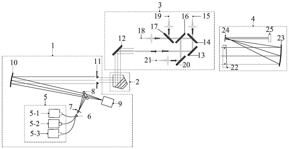
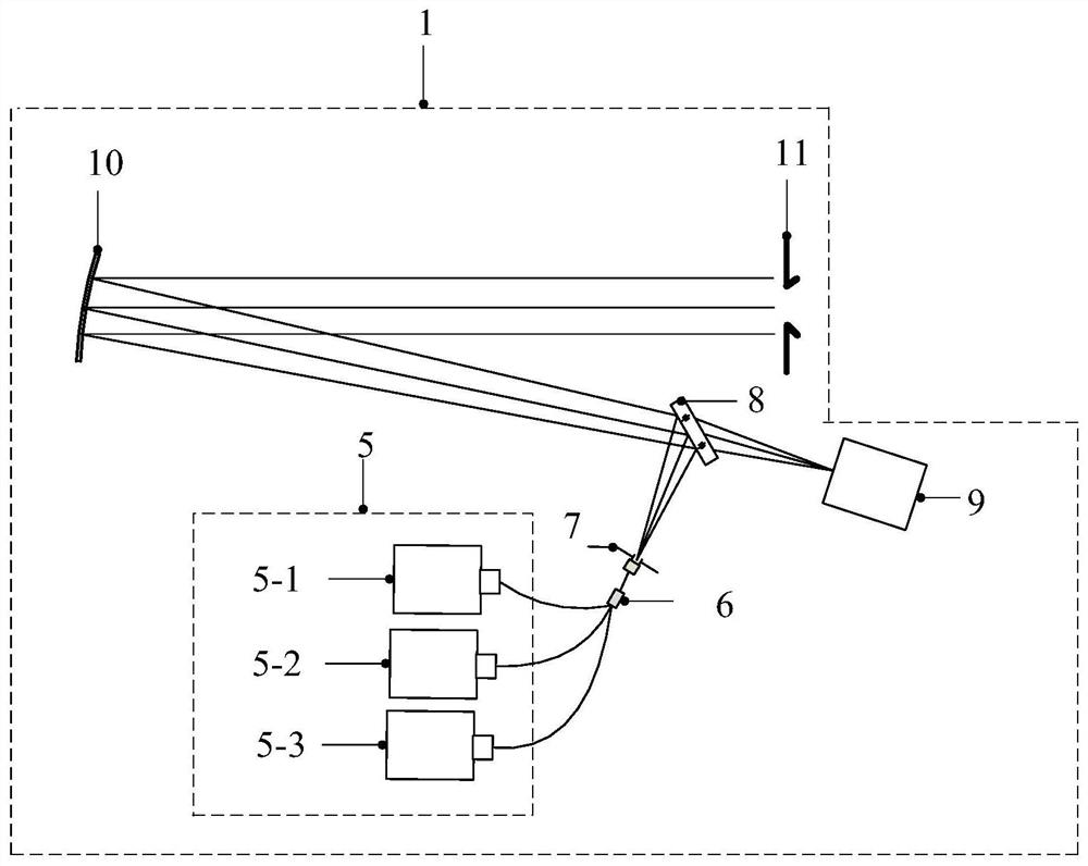
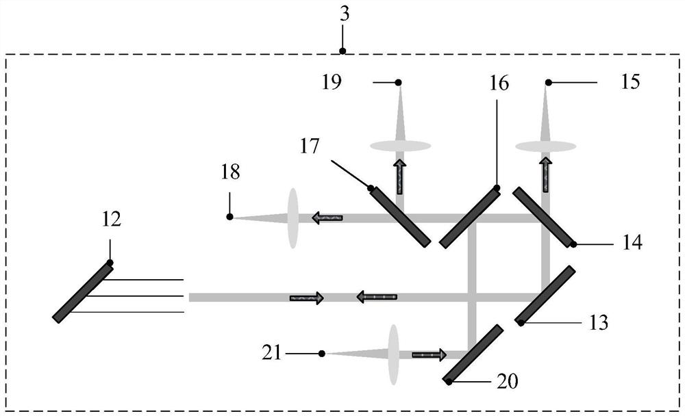
[0064] combine Figure 1 to Figure 4 , the installation and inspection system of the optical path relay unit of the laser communication terminal in this embodiment includes a transceiver alignment module 1 , a rotation module 2 and a reception and interpretation module 4 arranged in sequence along the optical path. from Figure 4 It can be seen that the relay unit 3 under test is fixed on the rotating module 2, the optical axis of the transmitting and receiving collimating module 1 is perpendicular to the rotating axis of the rotating module 2, and the optical axis of the transmitting and receiving collimating module 1 is perpendicular to the optical axis of the receiving and interpreting module 4 , the optical axis of the receiving and interpreting module 4 is also perpendicular to the rotating axis of the rotating module 2 .

[0065] from ...


PUM


Abstract

The invention belongs to the field of optical installation and adjustment, and relates to a laser communication terminal optical path relay unit installation and inspection system and a detection method based on it, which solves the problem that the existing test system cannot distinguish the coaxiality of the transmitting and receiving beams of each branch of the relay optical path Question, the system includes a transceiver collimation module, a rotating module and a receiving and interpreting module arranged in sequence along the optical path; the transmitting and receiving collimating module is used to emit collimated light beams, and receive and interpret the reflected light passing through the receiving and interpreting module; the rotating module is used to install The relay unit under test realizes the pointing adjustment of each branch in the relay unit under test; the receiving and interpreting module is used for receiving, interpreting and reflecting the output beam of the relay unit under test; the method of the invention can realize the relaying of laser communication terminals The fast and efficient assembly and integration of the unit completes the detection of divergence angle, coaxiality and other indicators of the relay unit.

Description

technical field [0001] The invention belongs to the field of optical installation and adjustment, and relates to an installation and inspection system for an optical path relay unit of a laser communication terminal and a detection method based on it, in particular to a pointing accuracy and coaxiality of each branch of an optical path relay unit of a space laser communication terminal Controlled batch, high-efficiency assembly and inspection system. Background technique [0002] Space high-speed laser communication is the core technology for building a space information network. In recent years, the United States, Europe, Japan, Russia and other countries have been competing to develop in this field. National research and development institutions such as NASA, ESA, and JAXA have successively achieved on-orbit demonstrations. China has also deployed a number of related research and development programs in related fields, and realized the on-orbit demonstration and verificati...

Claims


Application Information

Patent Timeline
Patent Type & Authority Patents(China)
IPC IPC(8): H04B10/11H04B10/077H04B10/291G02B27/62
CPCG02B27/62H04B10/077H04B10/0777H04B10/11H04B10/291
Inventor 薛勋赵建科周艳李晶王争锋刘锴曹昆昌明刘尚阔焦璐璐鄂可伟
Owner XI'AN INST OF OPTICS & FINE MECHANICS - CHINESE ACAD OF SCI
Learn More