Compact redundant built-in magnetostriction displacement sensor
A displacement sensor and magnetostrictive technology, applied in the direction of instruments, measuring devices, electrical devices, etc., can solve the problems that the built-in magnetostrictive displacement sensor cannot be replaced or easily replaced, and the requirements for measurement stability are high, achieving compact structure, The effect of good compatibility and high reliability
- Summary
- Abstract
- Description
- Claims
- Application Information
AI Technical Summary
Problems solved by technology
Method used
Image
Examples
Embodiment 1
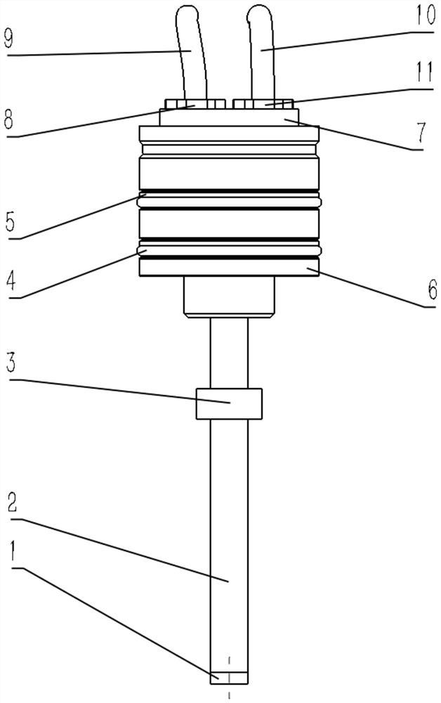
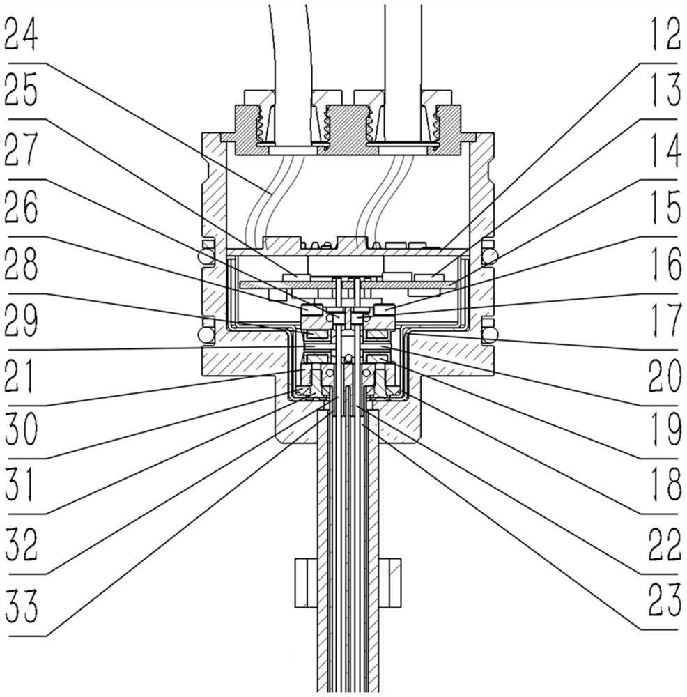
[0029] Such as Figure 1-2 As shown, this embodiment provides a compact redundant built-in magnetostrictive displacement sensor, the compact redundant built-in magnetostrictive displacement sensor includes a housing, a first redundant sensor element, a second redundant sensor element, a measurement Rod 2 and magnetic ring 3, the measuring rod 2 is connected to the lower end of the housing, the magnetic ring 3 is slidably sleeved on the outer periphery of the measuring rod 2, the first redundant sensor element and the second Redundant sensor elements are arranged side by side in the housing and the measuring rod 2 .
[0030] The first redundant sensor element and the second redundant sensor element in this embodiment have independent power supply and signal output systems, and the two systems can work independently regardless of primary or secondary.
[0031] There are three working modes:
[0032] In the same signal output mode, the signal types and effective signal ranges o...
Embodiment 2
[0038] Such as Figure 1-2 As shown, the compact redundant built-in magnetostrictive displacement sensor also includes a first wiring harness 9, a second wiring harness 10, an internal wiring harness 24, a first compression screw 8 and a second compression screw 11, and the housing includes electronic Compartment 6 and electronic compartment tail cover 7, the internal wiring harness 24 is located in the housing, the lower end of the electronic compartment 6 is connected to the measuring rod 2, and the upper end is open, and the electronic compartment tail cover 7 covers the electronic compartment 6 The upper end of the upper end is open, the first wire harness 9 and the second wire harness 10 are respectively connected to the electronic compartment tail cover 7 through the first compression screw 8 and the second compression screw 11 in parallel from top to bottom, and the first The wire harness 9 and the second wire harness 10 are respectively connected to the first redundant...
Embodiment 3
[0041] Such as Figure 1-2 As shown, the outer circumference of the housing is provided with retaining rings 5 and O-rings 4 at intervals from top to bottom, and the lower end of the measuring rod 2 is sealed by the end cap 1 . In this embodiment, the retaining ring 5 and the O-ring 4 are provided to facilitate the installation, fixation and sealing of the housing, and the sealing of the lower end of the measuring rod 2 is facilitated through the end cap 1 .
PUM
 Abstract
Description
Claims
Application Information
 - R&D Engineer
- R&D Manager
- IP Professional
- Industry Leading Data Capabilities
- Powerful AI technology
- Patent DNA Extraction
Browse by: Latest US Patents, China's latest patents, Technical Efficacy Thesaurus, Application Domain, Technology Topic, Popular Technical Reports.
© 2024 PatSnap. All rights reserved.Legal|Privacy policy|Modern Slavery Act Transparency Statement|Sitemap|About US| Contact US: help@patsnap.com


