Ice making box
An ice-making box and main body technology, applied in the field of ice-making equipment manufacturing, can solve problems such as long ice-making time, unqualified ice cubes, and low ice-making efficiency
- Summary
- Abstract
- Description
- Claims
- Application Information
AI Technical Summary
Problems solved by technology
Method used
Image

Examples
Embodiment 1
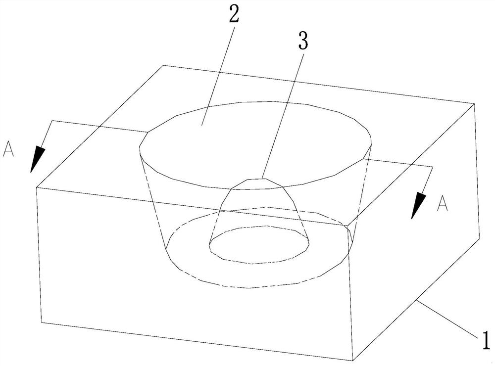
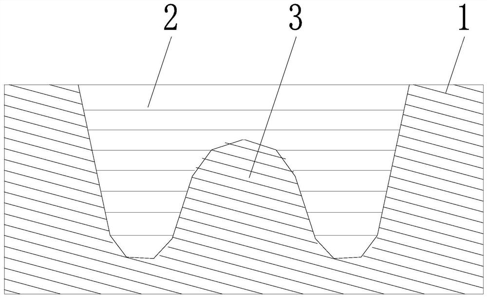
[0033] see figure 1 and figure 2 , an ice-making box, comprising an ice-making box main body 1, a groove 2 is opened on the surface of the ice-making box main body 1, the groove 2 is used to hold water for making ice cubes, and the bottom of the groove 2 is provided with A protruding part 3, the protruding part 3 is integrally formed with the main body of the ice box 1, the bottom surface of the ice box is flat, used to receive the cold energy required for ice making, the wall surface of the groove 2 and the surface of the protruding part 3 are connected with water , to realize the conduction of the cooling capacity of the ice box to the water, so that the water cooling capacity conduction surface in the groove 2 is not only the inner wall surface of the groove 2, but also the surrounding surface of the raised part 3, so that the heat exchange area is increased. At the same time, the cold energy is changed from the simple one-way conduction of the wall surface of the groove ...
Embodiment 3
[0046] see Figure 8 , Figure 9 and Figure 10 , an ice making box, comprising an ice making box main body 1, the ice making box main body 1 is provided with a groove 2, the groove 2 is used to hold water for making ice cubes, and the groove 2 is provided with There is a raised portion 3, such as Figure 8 As shown, the shape of the raised portion 3 is trapezoidal, and it can also be as Figure 9 As shown, the shape of the raised portion 3 is a rectangle, and it can also be as Figure 10 As shown, the shape of the raised portion 3 is an irregular shape, which can be designed according to the shape of ice making required. The raised portion 3 and the main body 1 of the ice box are integrally formed, and the ice box The bottom surface of the box is a plane, which is used to receive the cold energy required for ice making. The wall surface of the groove 2 and the surface of the raised part 3 are connected to the water to realize the cold energy conduction from the ice box to...
Embodiment 4
[0055] see Figure 11 and Figure 12 , from the comprehensive perspectives of ice-making speed, economy, volume, and matching with the cold surface of semiconductor refrigeration chips, an ice-making box includes a main body 1 of the ice-making box, and the main body 1 of the ice-making box is provided with a groove 2, The number of the grooves 2 can be four, and the grooves 2 are used to hold water for making ice cubes, and each of the grooves 2 is provided with a protrusion 3, and the protrusions The part 3 and the main body 1 of the ice box are integrally formed. The bottom surface of the ice box is flat to receive the cooling capacity required for ice making. The wall surface of the groove 2 and the surface of the raised part 3 are connected with water to realize ice making. The cooling capacity of the box is transferred to the cooling capacity of the water, so that the water cooling capacity conduction surface in the groove 2 is not only the inner wall surface of the gro...
PUM
| Property | Measurement | Unit |
|---|---|---|
| Thermal conductivity | aaaaa | aaaaa |
Abstract
Description
Claims
Application Information
 - R&D
- Intellectual Property
- Life Sciences
- Materials
- Tech Scout
- Unparalleled Data Quality
- Higher Quality Content
- 60% Fewer Hallucinations
Browse by: Latest US Patents, China's latest patents, Technical Efficacy Thesaurus, Application Domain, Technology Topic, Popular Technical Reports.
© 2025 PatSnap. All rights reserved.Legal|Privacy policy|Modern Slavery Act Transparency Statement|Sitemap|About US| Contact US: help@patsnap.com