Annular casing pipe type heat exchanger

A heat exchanger, sleeve type technology, applied in the field of heat exchange, can solve the problems of easy blockage of the heat exchanger flow channel, insignificant heat recovery economic benefits, large temperature difference at the hot end of the heat exchanger, etc., and achieves a small occupied space. , The effect of strong pressure bearing capacity and sufficient heat exchange

Inactive Publication Date: 2017-07-04
刘洋豪
View PDF5 Cites 0 Cited by
  • Summary
  • Abstract
  • Description
  • Claims
  • Application Information

AI Technical Summary

Problems solved by technology

[0002] In daily life and industrial production, in order to improve the heat exchange efficiency of the heat exchanger, the diameter of the flow channel of the heat exchanger should be made as small as possible. The flow channel is easily blocked; at the same time, the flow channel of the heat exchanger is short, and the temperature difference at the hot end of the heat exchanger is large (the temperature difference at the hot end refers to the temperature difference between when the hot medium flows into the heat exchanger and when the cold medium flows out of the heat exchanger), and the heat recovery efficiency is low , the economic benefit of heat recovery is not significant, and the problem of heat energy recovery of waste hot water in family bathing, beauty salons, large bathing centers and industrial production has not been well solved.

Method used


Image

  • Annular casing pipe type heat exchanger

Examples


Embodiment Construction

[0013] The present invention will be further described below in conjunction with accompanying drawing.

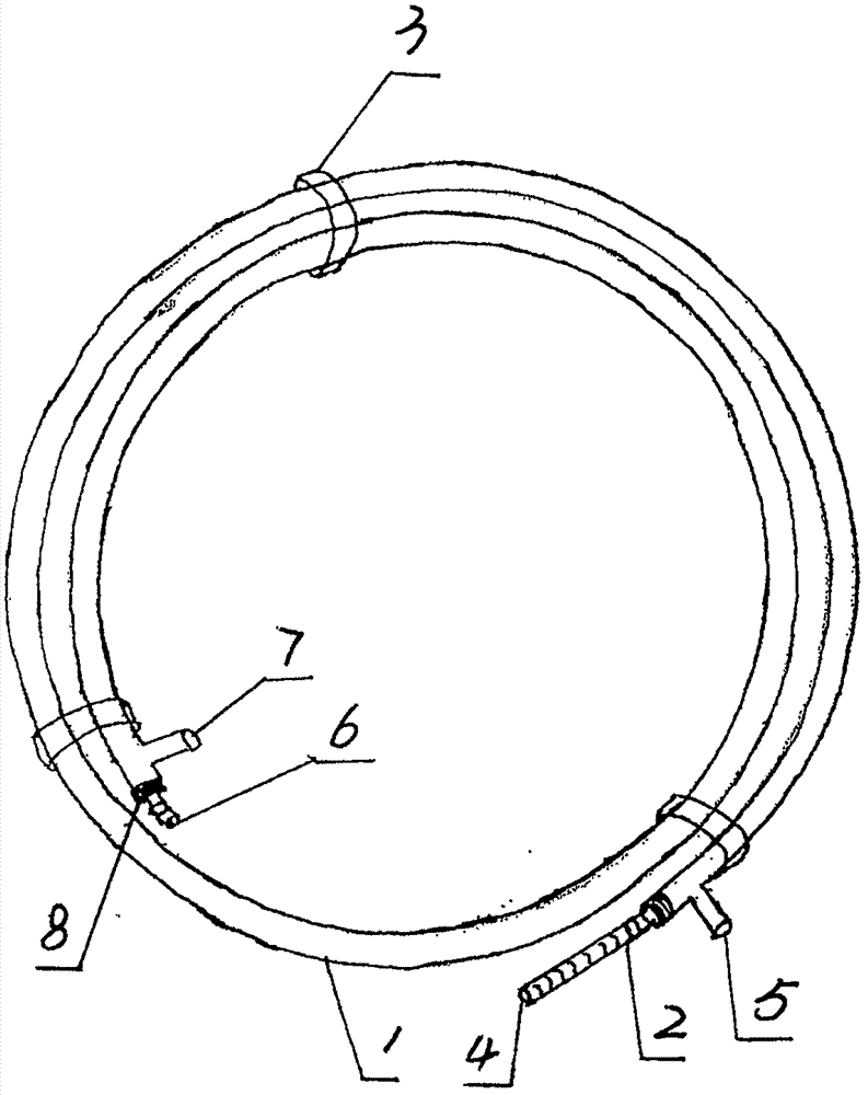
[0014] An annular casing heat exchanger according to the present invention includes a plastic pipe 1, a stainless steel bellows 2 and a binding piece 3, and is characterized in that a stainless steel bellows 2 is installed in the plastic pipe 1, and the stainless steel bellows The openings at both ends of the plastic pipe 1 are exposed outside the openings at both ends of the plastic pipe 1, and the openings at both ends of the plastic pipe 1 and the outer wall of the stainless steel corrugated pipe 2 are sealed by injection molding, hot melting, welding or colloid; a hole is opened on the wall at one end of the plastic pipe 1 , through injection molding, hot melting, welding or colloid sealing, install the first interface 4 on the opening of the pipe wall, open a hole on the other end of the plastic pipe 1, and seal it through injection molding, hot melting, welding or coll...


PUM


Abstract

The invention provides an annular casing pipe type heat exchanger. The annular casing pipe type heat exchanger comprises a plastic pipe, a stainless steel corrugated pipe and bundling pieces. The annular casing pipe type heat exchanger is characterized in that the stainless steel corrugated pipe is arranged in the plastic pipe, openings in the two ends of the stainless steel corrugated pipe are exposed out of openings in the two ends of the plastic pipe, and the openings in the two ends of the plastic pipe and the outer wall of the stainless steel corrugated pipe are sealed through injection molding or hot melting or welding or glue; a hole is formed in the pipe wall at one end of the plastic pipe, and a first connector is arranged on the hole in the pipe wall in the manner of injection molding or hot melting or welding or glue; a hole is formed in the pipe wall at the other end of the plastic pipe, a second connector is arranged on the hole of the pipe wall, the opening in one end of the stainless steel corrugated pipe is provided with a third connector, and the opening in the other end of the stainless steel corrugated pipe is provided with a fourth connector; and the plastic pipe provided with the stainless steel corrugated pipe is manufactured into a spiral shape, and the plastic pipe is twisted by the bundling pieces to be shaped into a ring shape. Waste hot water flows through the stainless steel corrugated pipe with the diameter ranging from 10 mm to 70 mm, blockage is not likely to happen, and the heat energy of the waste hot water can be better recycled.

Description

technical field [0001] The invention relates to the field of heat exchange, in particular to an annular sleeve heat exchanger. Background technique [0002] In daily life and industrial production, in order to improve the heat exchange efficiency of the heat exchanger, the diameter of the flow channel of the heat exchanger should be made as small as possible. The flow channel is easily blocked; at the same time, the flow channel of the heat exchanger is short, and the temperature difference at the hot end of the heat exchanger is large (the temperature difference at the hot end refers to the temperature difference between when the hot medium flows into the heat exchanger and when the cold medium flows out of the heat exchanger), and the heat recovery efficiency is low However, the economic benefit of heat recovery is not significant, and the problem of heat energy recovery of waste hot water in family bathing, beauty salons, large bath centers and industrial production has n...

Claims


Application Information

Patent Timeline
Patent Type & Authority Applications(China)
IPC IPC(8): F28D7/10
CPCF28D7/10
Inventor 刘洋豪刘兴波
Owner 刘洋豪
Why Eureka
Try Eureka