
Constant-pressure clamping device for processing of strip-shaped optical glass

A technology of optical glass and clamping device, which is applied in the direction of workpiece clamping device, manufacturing tools, etc., can solve the problems of processing failure, inability to guarantee the clamping and fixing of optical glass, and insufficient clamping, so as to avoid the effect of loss

Pending Publication Date: 2021-04-27
吴懋萱
View PDF0 Cites 7 Cited by
  • Summary
  • Abstract
  • Description
  • Claims
  • Application Information

AI Technical Summary

Problems solved by technology

[0003] Optical glass needs to be clamped and fixed during processing. Rigid clamping is generally used in the prior art. During the clamping process, the splint is in direct rigid contact with the optical glass. If the clamping force is too large, it is easy to distort the optical glass. The glass is broken, but if the clamping force is too small, the clamping will not be firm enough. During the processing, the optical glass is easy to move, resulting in low processing accuracy, or even processing failure, resulting in the scrapping of the optical glass. produce
[0004] When clamping and fixing devices in the prior art are clamping, it is difficult to grasp the clamping force, but in the process of clamping optical glass, there is an optimal clamping force, that is, an optimal clamping pressure , in the prior art, the optical glass cannot be clamped and fixed under the optimal clamping pressure condition

Method used


Image

  • Constant-pressure clamping device for processing of strip-shaped optical glass
  • Constant-pressure clamping device for processing of strip-shaped optical glass
  • Constant-pressure clamping device for processing of strip-shaped optical glass

Examples


Embodiment Construction

[0035] The following will clearly and completely describe the technical solutions in the embodiments of the present invention with reference to the accompanying drawings in the embodiments of the present invention. Obviously, the described embodiments are only some, not all, embodiments of the present invention. Based on the embodiments of the present invention, all other embodiments obtained by persons of ordinary skill in the art without creative efforts fall within the protection scope of the present invention.

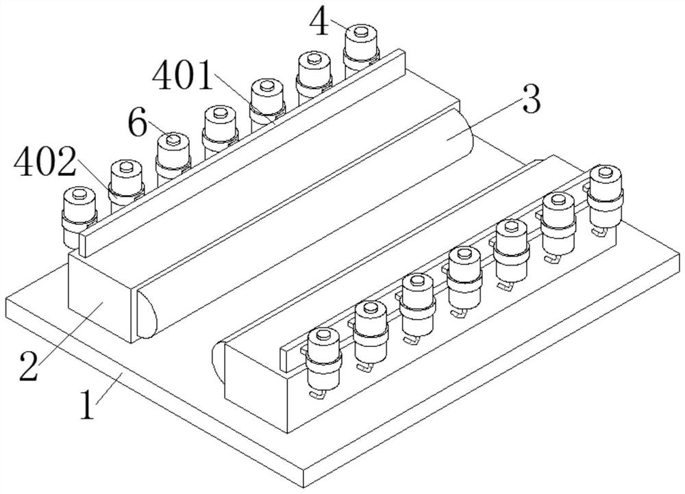
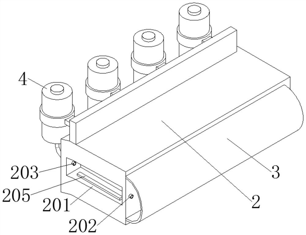
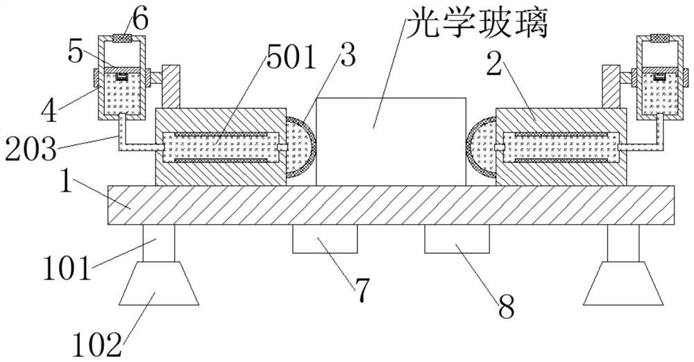
[0036] Such as Figure 1-6 As shown, a constant pressure clamping device for strip-shaped optical glass processing includes a base 1, a mounting base 2, a clamping air bag 3, a liquid storage cylinder 4, a piston 5 and an electromagnet 6; the base 1 is rectangular, and the mounting base 2 Left and right symmetrically fixed on the upper surface of the base 1, the mounting base 2 is parallel to the length direction of the base 1, and the two mounting bases 2 are arra...


PUM


Abstract

The invention discloses a constant-pressure clamping device for processing of strip-shaped optical glass. The constant-pressure clamping device comprises a base, mounting seats, a clamping air bag, a liquid storage cylinder, a piston and an electromagnet. In the using process, to-be-processed optical glass is placed between the mounting seats, in the initial state, due to the fluidity of fluid and the elasticity of the clamping air bag, the optical glass can be smoothly placed, and thus the optical glass in different sizes can be conveniently placed between the mounting seats; then the electromagnet is electrified, the electromagnet generates magnetism when electrified, the polarities of the sides, close to each other, of the piston and the electromagnet are the same, the magnetic repulsion force between the electromagnet and the piston drives the piston to descend, thus the fluid is squeezed into the clamping air bag, the clamping air bag is expanded, and thus the optical glass is fixed and clamped; and the optical glass is clamped through the flexible clamping air bag, thus the enough clamping force can be kept, and the circumstance that the optical glass is damaged in the clamping process can also be avoided.

Description

technical field [0001] The invention relates to the technical field of optical glass processing devices, in particular to a constant pressure clamping device for strip optical glass processing. Background technique [0002] Optical glass is a glass material used to manufacture lenses, prisms, mirrors, windows, etc. of optical instruments or mechanical systems, including colorless optical glass, colored optical glass, radiation-resistant optical glass, radiation-resistant glass and optical quartz glass, etc. Optical glass has high transparency, high chemical and physical uniformity, and specific and precise optical constants. It can be divided into silicate, borate, phosphate, fluoride and chalcogenide series. [0003] Optical glass needs to be clamped and fixed during processing. Rigid clamping is generally used in the prior art. During the clamping process, the splint is in direct rigid contact with the optical glass. If the clamping force is too large, it is easy to distor...

Claims


Application Information

Patent Timeline
Patent Type & Authority Applications(China)
IPC IPC(8): B25B11/00
CPCB25B11/00
Inventor 吴懋萱
Owner 吴懋萱
Learn More