Method for improving performance of depolarizer, depolarizer and mixed polarization fiber-optic gyroscope

A fiber optic gyroscope and depolarizer technology, which is applied to Sagnac effect gyroscopes, gyroscopes/steering sensing devices, instruments, etc., can solve the problem that the depolarization effect cannot be monitored and improved, and the depolarization effect is not ideal, etc. question

Active Publication Date: 2021-04-23
HUBEI SANJIANG AEROSPACE HONGFENG CONTROL
View PDF6 Cites 0 Cited by
  • Summary
  • Abstract
  • Description
  • Claims
  • Application Information

AI Technical Summary

Problems solved by technology

In the mixed-polarization fiber optic gyro optical path, since the depolarizer is made of the input optical fiber that comes with the Y waveguide, the two sections of optical fiber are fused at 45° to the axis, and the depolarized optical signal directly enters the Y waveguide for polarization. ° The depolarization effect of the axis cannot be monitored and improved, resulting in unsatisfactory depolarization effect

Method used


Image

  • Method for improving performance of depolarizer, depolarizer and mixed polarization fiber-optic gyroscope
  • Method for improving performance of depolarizer, depolarizer and mixed polarization fiber-optic gyroscope
  • Method for improving performance of depolarizer, depolarizer and mixed polarization fiber-optic gyroscope

Examples


Embodiment Construction

[0025] In order to make the object, technical solution and advantages of the present invention clearer, the present invention will be further described in detail below in conjunction with the accompanying drawings and embodiments. It should be understood that the specific embodiments described here are only used to explain the present invention, not to limit the present invention. In addition, the technical features involved in the various embodiments of the present invention described below can be combined with each other as long as they do not constitute a conflict with each other.

[0026] The working principle of a method for improving the performance of the depolarizer provided by the present invention will be described in detail below with reference to the embodiments and the accompanying drawings.

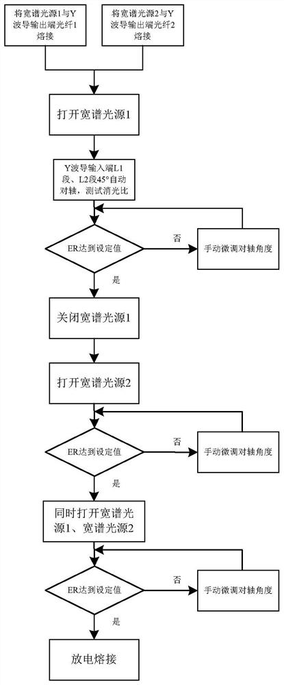
[0027] figure 1 is a schematic diagram of a method for improving the performance of a depolarizer provided by an embodiment of the present invention. Such as figure 1 As ...


PUM

PropertyMeasurementUnit
wavelengthaaaaaaaaaa

Abstract

The invention discloses a method for improving the performance of a depolarizer, the depolarizer and a mixed polarization fiber-optic gyroscope, which are characterized in that a first wide-spectrum light source is welded with a first output end optical fiber of a Y-shaped waveguide, a second wide-spectrum light source is welded with a second output end optical fiber of the Y-shaped waveguide, and an extinction ratio tester is connected to a first polarization maintaining optical fiber; only the first wide-spectrum light source is turned on, and the 45-degree countershaft angle of the first polarization maintaining optical fiber and the second polarization maintaining optical fiber is adjusted, so that the first extinction ratio is smaller than a preset first threshold value; only the second wide-spectrum light source is turned on, and the 45-degree countershaft angle of the first polarization maintaining optical fiber and the second polarization maintaining optical fiber is adjusted, so that the second extinction ratio is smaller than a preset second threshold value; when the third extinction ratio is smaller than a preset third threshold value, 45-degree opposite axis points of the first polarization maintaining optical fiber and the second polarization maintaining optical fiber are subjected to discharge welding, and the two output ends of the Y waveguide are connected with the wide-spectrum light source for reverse light transmission monitoring; and optical signals transmitted clockwise and anticlockwise in an optical fiber ring of the fiber-optic gyroscope are simulated, and the improvement of the effect of the depolarizer is more suitable for practical application.

Description

technical field [0001] The invention belongs to the technical field of optical fiber communication, and more specifically relates to a method for improving the performance of a depolarizer, a depolarizer and a mixed-polarization fiber optic gyroscope. Background technique [0002] The fiber optic gyroscope is an inertial instrument based on the Sagnac effect, which can measure the rotational angular velocity relative to the inertial space. Because there are no moving parts in the composition structure, it has small size, light weight, and wide precision coverage, and has been widely used in various fields such as land, sea, air, and space. As the sensitive and detection part of the Sagnac effect, the gyro optical path is the core component of the fiber optic gyro. The mixed polarization optical path is a form of optical path of the fiber optic gyroscope. In the mixed polarization optical path, a depolarizer is added between the single-mode fiber coupler and the Y waveguide...

Claims


Application Information

Patent Timeline
Patent Type & Authority Applications(China)
IPC IPC(8): G01C19/72
CPCG01C19/721
Inventor 郭礼芹路青梅程成康希伦彭志强李亮
Owner HUBEI SANJIANG AEROSPACE HONGFENG CONTROL
Why Eureka
Try Eureka