Airflow spray mouth

A technology of airflow nozzles and nozzles, which is applied in the field of combustion to achieve the effect of uniform fuel film and eliminating sealing problems

Inactive Publication Date: 2003-11-05
ALSTOM TECH LTD
View PDF0 Cites 0 Cited by
  • Summary
  • Abstract
  • Description
  • Claims
  • Application Information

AI Technical Summary

Problems solved by technology

The disadvantage of this plunger body is that it will result in a particular susceptibility to coking and dope formation in the downstream

Method used


Image

  • Airflow spray mouth
  • Airflow spray mouth
  • Airflow spray mouth

Examples


Embodiment Construction

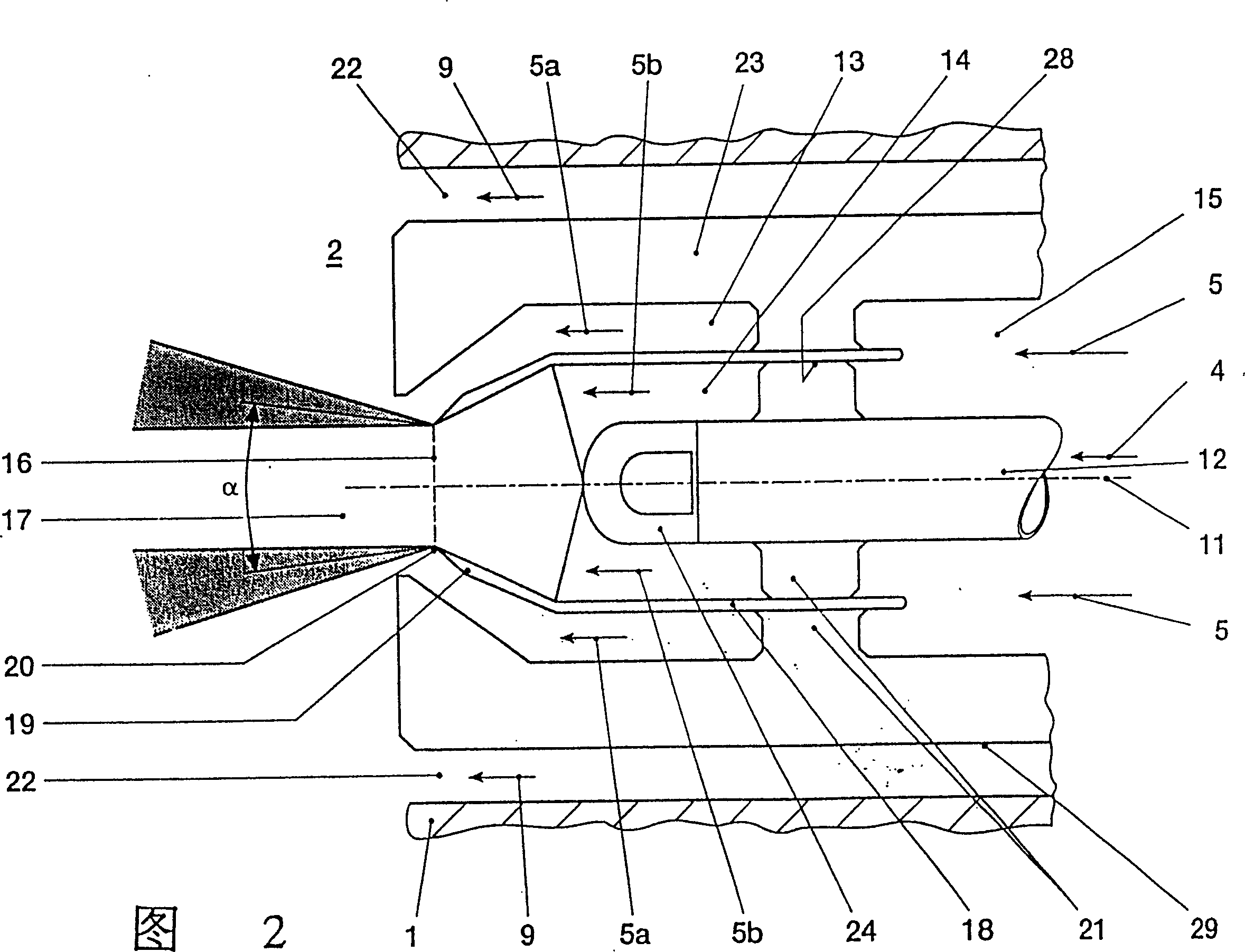
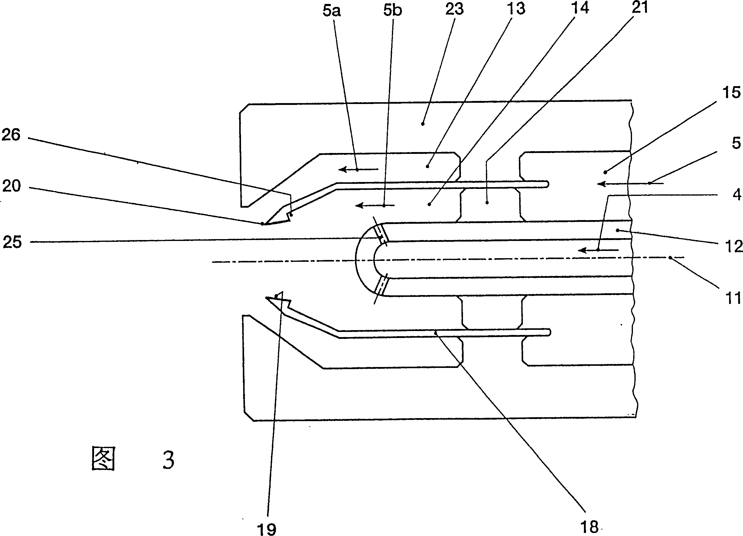
[0030] Below will contrast embodiment and appended figure 1 To 7, the present invention is further described.

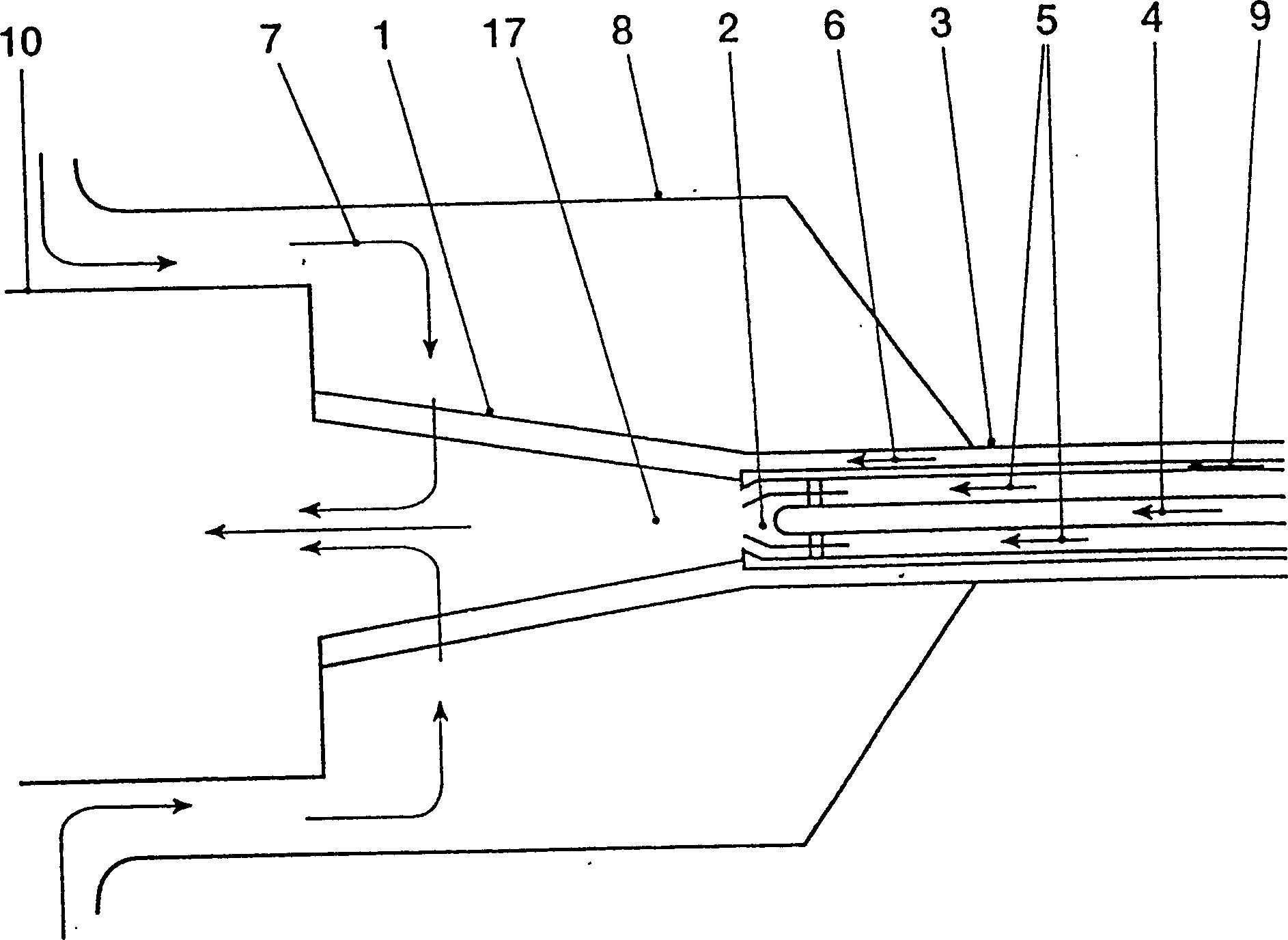
[0031] figure 1 Schematic of the setup for a biconical premixed fuel injector equipped with an airflow nozzle.

[0032] An air flow nozzle 2 is provided at the upstream end of the burner 1 . The nozzle is supplied with liquid fuel 4 and compressed air 5 via a fuel nozzle 3 connected to the double-cone burner 1 and used for atomizing the fuel 4 . In addition, the fuel nozzle 3 also delivers gaseous fuel 6 to the double-cone fueler 1 , while the gaseous fuel obtains main fueler air 7 from a cavity in the burner housing 8 . The air for the gas flow nozzles 2 can also be supplied by a pressure through system (not shown in the figure) located outside the burner housing 8 . In addition, in this embodiment, additional gaseous fuel (auxiliary gas 9 ) is injected into the burner 1 through the fuel nozzle 3 in order to lubricate the gas near the axis of the nozzle of the d...


PUM


Abstract

Partition between the inner gas path (14) and the outer gas path (13) in an airflow-atomizer nozzle (2) for operation of a burner (1) operating with liquid and gaseous fuels (4, 6) (18) is secured by inner and outer supports (21), which may have a slip fit (28) and may be turbine blade construction. The sprayer edge (19) of the airflow nozzle (2) is inclined relative to the direction of the nozzle axis (11). The nozzles are characterized by small dimensions, low pressure loss and are not prone to coking.

Description

technical field [0001] The invention relates to the technical field of combustion. It relates to a nozzle for atomizing liquid fuel in a burner, which works on the principle of air flow, it is suitable for both burners operating with liquid fuel and for fuel burners operating with gaseous fuel, and especially It can be used in premixed burners with low harmful substances in double cone structure. Background technique [0002] In order to achieve premixed fuel with low harmful substances, the fuel must be uniformly mixed with the combustion air before combustion. When liquid fuel is used, the fuel must be pre-atomized. In this case, the liquid fuel jet is divided into individual particles, so that the largest possible vaporization surface is obtained for the fuel. [0003] In order to realize the atomization of the liquid fuel in the fuel chamber, a so-called airflow atomizer (see: A.H.Lefebvre, Airblast Atomization, Prog.EnergyCombust.Sci.Vol.6, S.233-261, 1980) is also u...

Claims


Application Information

Patent Timeline
Patent Type & Authority Patents(China)
IPC IPC(8): F23D11/10F23D11/40F23D11/00
CPCF23C2900/07002F23D11/007F23D11/107F23D2211/00F23D2900/11101
Inventor F·朱斯M·施塔尔德
Owner ALSTOM TECH LTD
Why Eureka
Try Eureka