Bidirectional converter

A technology of bidirectional converters and transformers, which is applied in the direction of instruments, DC power input conversion to DC power output, AC power input conversion to DC power output, etc., which can solve the problem of narrowing the output voltage range, reducing conversion efficiency, reducing voltage gain, etc. problem, achieve the effect of realizing voltage range output, increasing output voltage range, and wide voltage range output

Pending Publication Date: 2021-04-20
深圳深源技术能源有限公司
View PDF0 Cites 2 Cited by
  • Summary
  • Abstract
  • Description
  • Claims
  • Application Information

AI Technical Summary

Problems solved by technology

[0003] In the traditional LLC resonant bidirectional converter, the ZVS conduction of the switch tube on the primary side and the ZCS conduction of the diode on the rectification side can be realized regardless of forward and reverse operation, but its circuit characteristics are no longer when the energy flows in the reverse direction. It is the LLC resonance characteristic and degenerates into the LC resonance characteristic. The maximum voltage gain of the LC resonance becomes 1, which greatly reduces the voltage gain during reverse operation, greatly narrows the output voltage range, and intensifies the soft switching of the switching tube. Difficulty, which reduces the conversion efficiency, so it is not suitable for working in the state of bidirectional flow of energy in a wide range, which limits its application scenarios

Method used


Image

  • Bidirectional converter
  • Bidirectional converter

Examples


Embodiment Construction

[0016] In order to make those skilled in the art more clearly understand the purpose, technical solutions and advantages of the present invention, the present invention will be further described below in conjunction with the accompanying drawings and embodiments.

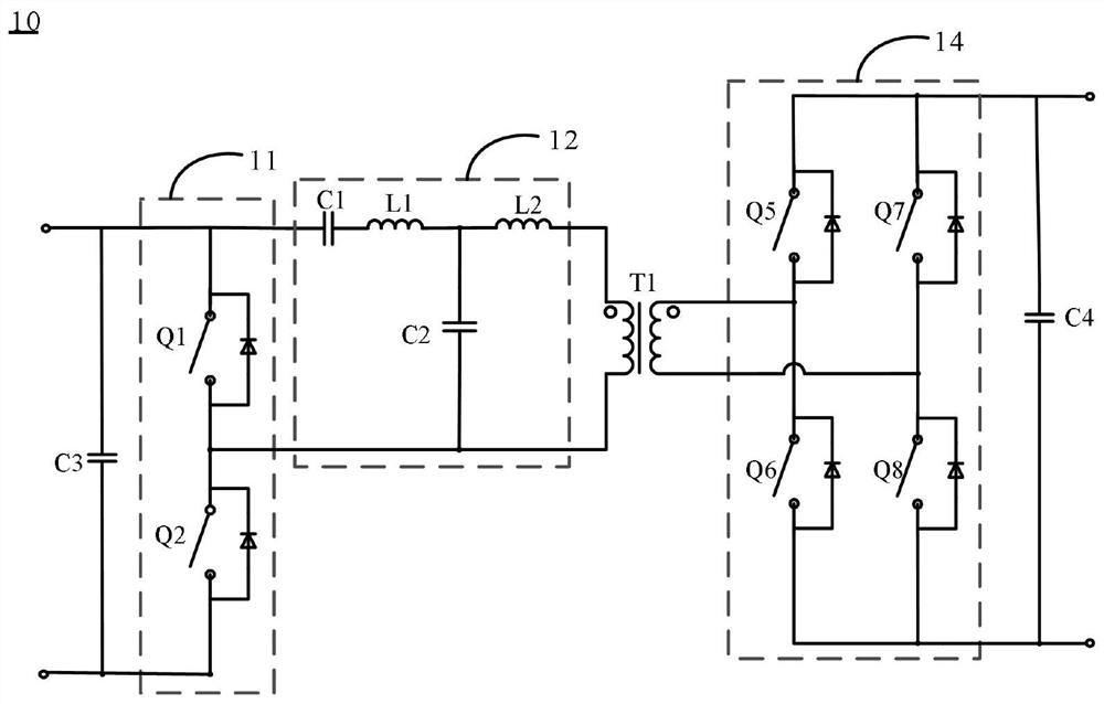
[0017] refer to figure 1 , figure 1 It is a schematic circuit diagram of the first embodiment of the bidirectional converter 10 of the present invention. In the embodiment shown in the drawings, the bidirectional converter 10 includes an inverter circuit 11, a resonant circuit 12, a transformer T1, and a rectifier circuit 14, wherein the inverter circuit 11 is a half-bridge structure, specifically, this In the embodiment, the inverter circuit 11 includes two switching tubes, the first switching tube Q1 and the second switching tube Q2, the first switching tube Q1 and the second switching tube Q2 are connected in series to form a bridge arm, and the resonant circuit 12 It includes a first capacitor C1, a second cap...


PUM


Abstract

The invention discloses a bidirectional converter. The bidirectional converter comprises an inverter circuit, a resonance circuit, a transformer and a rectification circuit, wherein the inverter circuit is a half-bridge inverter circuit and comprises two switching tubes; the two switching tubes are connected in series to form a bridge arm; the resonance circuit comprises a first capacitor, a second capacitor, a first inductor and a second inductor; one end of the first inductor is connected with the second inductor and one end of the second capacitor; one end of the first capacitor is connected with the other end of the first inductor; the other end of the first capacitor and the other end of the second capacitor are connected to the bridge arm of the inverter circuit; the other end of the second capacitor and the other end of the second inductor are connected with a primary winding of a transformer; a secondary winding of the transformer is connected with the input side of the rectification circuit; and the output side of the rectification circuit and the two ends of the bridge arm of the inversion circuit serve as the second external connection end and the first external connection end of the bidirectional converter respectively.

Description

technical field [0001] The present invention relates to the technical field of power conversion, and more particularly relates to a bidirectional converter. Background technique [0002] The bidirectional isolated DC-DC converter is a DC / DC converter that can adjust the bidirectional transmission of energy according to the needs. It is mainly used in energy storage systems, vehicle power systems, feedback charging and discharging systems, hybrid energy electric vehicles and other occasions. [0003] In the traditional LLC resonant bidirectional converter, the ZVS conduction of the switch tube on the primary side and the ZCS conduction of the diode on the rectification side can be realized regardless of forward and reverse operation, but its circuit characteristics are no longer when the energy flows in the reverse direction. It is the LLC resonance characteristic and degenerates into the LC resonance characteristic. The maximum voltage gain of the LC resonance becomes 1, whi...

Claims


Application Information

Patent Timeline
IPC IPC(8): H02M3/335H02M7/797H02M1/088
Inventor 王艳萍
Owner 深圳深源技术能源有限公司
Why Eureka
Try Eureka