A Reservoir Sediment Extraction System Based on Robot Algorithm to Shape Artificial Eddy
A technology of extraction system and robot, applied in mechanically driven excavators/dredgers, etc., can solve the problems of difficult adjustment, high energy consumption, low sediment suction efficiency, etc., to improve sand extraction efficiency, easy to control and save Effects of sand mining costs
- Summary
- Abstract
- Description
- Claims
- Application Information
AI Technical Summary
Problems solved by technology
Method used
Image
Examples
Embodiment 1
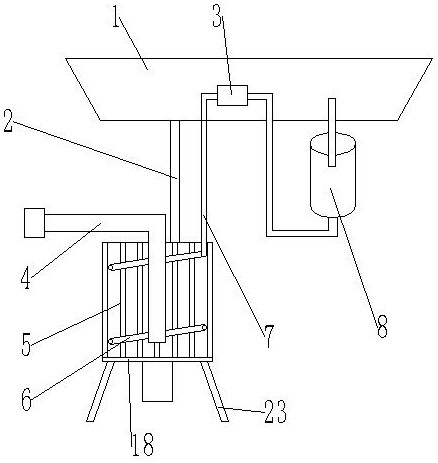
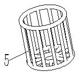
[0053] like Figure 1-5 As shown, a reservoir sediment pumping system based on robot algorithm to shape artificial vortex, comprises hull 1, and described hull 1 is provided with vortex former 18; Said vortex former 18 comprises water cage 5 and nozzle 6, and described Spout pipe 6 is arranged on the inner side of water cage 5, and described spray pipe 6 is connected with first water pump 8 by connecting pipe 7, and described connecting pipe 7 is flexible pipe, and described spray pipe 6 inside is provided with a plurality of shower nozzles 9; The inside of the water cage 5 is provided with a sediment pipe 4; the sediment pipe 4 is connected to the water inlet of the sediment pump, and the water outlet of the sediment pump is connected to an outlet pipe; the connecting pipe 7 is provided with a flow regulator 3 .
[0054]The upper and lower ends of the water cage 5 are provided with circular rings, and a plurality of connecting pipes are arranged between the circular rings, a...
Embodiment 2
[0060] Such as Figure 1-5 As shown, a reservoir sediment pumping system based on robot algorithm to shape artificial vortex, comprises hull 1, and described hull 1 is provided with vortex former 18; Said vortex former 18 comprises water cage 5 and nozzle 6, and described Spout pipe 6 is arranged on the inner side of water cage 5, and described nozzle pipe 6 is connected with the first water pump 8 through connecting pipe 7, and the inside of described nozzle pipe 6 is provided with a plurality of nozzles 9; The inside of described water cage 5 is provided with sediment pipe 4. The sand pipe 4 is connected to the water inlet of the sand pump, and the water outlet of the sand pump is connected to an outlet pipe; the connecting pipe 7 is provided with a flow regulator 3 . The hull 1 is provided with a hoist, and the wire rope of the hoist is connected with the connecting belt 2 . The position of the swirl former 18 at the bottom of the water is adjusted by setting the winch.
Embodiment 3
[0062] combine Figure 9 As shown, the difference from Embodiments 1 and 2 is that a motor support 19 is provided on the lower side of the water cage 5, a motor 20 is provided on the upper side of the motor support 19, and a fan blade 21 is connected to the output shaft of the motor 20. , the fan blade 21 is located inside the water cage 5, the motor 20 is a variable frequency motor, the motor 20 is provided with a waterproof device, the motor 20 drives the fan blade 21 to rotate, and cooperates with the first water pump 8 to adjust The size of the vortex, the vortex can fully stir the sediment at the bottom of the water, so that the sediment can be fully mixed with the water.
[0063] The upper side of the water cage 5 is provided with a sensor 22, and the sensor 22 is a force-sensitive sensor; the outside of the sensor 22 is provided with a waterproof device, and the sensor 22 is connected with the water cage 5 by a waterproof device, and the number of the sensors 22 is Mor...
PUM
 Abstract
Description
Claims
Application Information
 - R&D
- Intellectual Property
- Life Sciences
- Materials
- Tech Scout
- Unparalleled Data Quality
- Higher Quality Content
- 60% Fewer Hallucinations
Browse by: Latest US Patents, China's latest patents, Technical Efficacy Thesaurus, Application Domain, Technology Topic, Popular Technical Reports.
© 2025 PatSnap. All rights reserved.Legal|Privacy policy|Modern Slavery Act Transparency Statement|Sitemap|About US| Contact US: help@patsnap.com


