Efficient liquid oxygen storage tank transporting and putting equipment

A storage tank and liquid oxygen tank technology is applied in the field of efficient liquid oxygen storage tank transportation and delivery equipment, which can solve the problems of difficult automation, large vibration, and large volume of the tank.

Inactive Publication Date: 2021-04-20
南京鸿仕运贸易有限公司
View PDF0 Cites 0 Cited by
  • Summary
  • Abstract
  • Description
  • Claims
  • Application Information

AI Technical Summary

Problems solved by technology

[0004] At present, the long-distance transportation of liquid oxygen mainly relies on mature large tank transport vehicles, but in the short-distance dispersed transportation, it mainly relies on the separate transportation of small tanks, but it is inconvenient when loading and unloading, and the mass and volume of the tanks are different It is relatively large, there is no special loading and unloading tool, and there is no special storage slot during transportation. The vibration is relatively large, and it is mainly loaded and unloaded by manual or forklift trucks. There is a safety hazard of falling and leaking, because high-concentration oxygen is toxic, and acute oxygen poisoning may occur, and at this stage, large-scale forklifts are mainly diesel engines, and oxygen leakage is also prone to explosion and fire problems, and manual operation , time-consuming, labor-intensive, low in efficiency, and difficult to automate, aiming at the above shortcomings, the present invention improves

Method used


Image

  • Efficient liquid oxygen storage tank transporting and putting equipment
  • Efficient liquid oxygen storage tank transporting and putting equipment
  • Efficient liquid oxygen storage tank transporting and putting equipment

Examples


Embodiment Construction

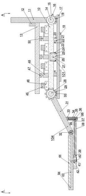
[0024] Combine below Figure 1-5 The present invention is described in detail, wherein, for the convenience of description, the orientations mentioned below are defined as follows: figure 1 The up, down, left, right, front and back directions of the projection relationship itself are the same.

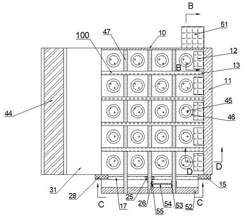
[0025] A high-efficiency liquid oxygen storage tank transportation and delivery equipment described in conjunction with accompanying drawings 1-5 includes a device bottom plate 10 and an erecting mechanism 100 and a power mechanism 101 arranged on the front side of the device bottom plate 10. The device bottom plate 10 The upper side is provided with a receiving mechanism 102 and a shock absorbing device 103, the left side of the device bottom plate 10 is provided with a tank loading mechanism 104, and the right side of the device bottom plate 10 is provided with a push-out mechanism 105;

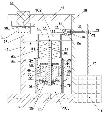
[0026] The power mechanism 101 includes a motor 24 fixedly positioned on the lower side of the ...


PUM


Abstract

The invention discloses efficient liquid oxygen storage tank transporting and putting equipment. The transporting and putting equipment comprises a device bottom plate, a vertical mechanism and a power mechanism, wherein the vertical mechanism and the power mechanism are arranged on the front side of the device bottom plate, and a containing mechanism and a damping device are arranged on the upper side of the device bottom plate. According to the transporting and putting equipment, a lifting device of a hydraulic structure and a loading device of a mechanical structure are used, the safety risk during oxygen leakage is greatly reduced, a special damping and anti-disengaging device is designed for each liquid oxygen tank on a containing frame, in order to reduce possible vibration of the tank body in the loading and unloading process, a transverse loading mode is adopted, the liquid oxygen tank is vertically placed after being put on a frame, the gravity center is lowered, the overturning risk is reduced as much as possible, when the liquid oxygen tank reaches a destination, the liquid oxygen tank can be vertically pushed down from the loading and unloading equipment through an automatic hydraulic push plate, the safety is greatly improved under the condition that the efficiency is guaranteed through combination of two loading and unloading modes, and meanwhile automation of the loading and unloading process is achieved, the treatment efficiency is greatly improved, and the labor force is saved.

Description

technical field [0001] The invention relates to a high-efficiency liquid oxygen storage tank transportation and delivery equipment, and mainly relates to the technical field of liquid oxygen tanks. Background technique [0002] Liquid oxygen storage tanks are mainly used for cryogenic liquid storage of oxygen, and one cubic meter of liquid can replace one hundred and thirty gas cylinders. It can replace the round-trip transport of gas cylinders every day, saving a lot of manpower and material resources. Widely used in the gas industry, hospitals, metal smelting and other users with large gas consumption, it is the best product to realize centralized gas supply. It has the characteristics of long service life, compact structure, small footprint, centralized control, and convenient operation; [0003] Liquid oxygen has a wide range of industrial and medical uses. Due to its low temperature characteristics, liquid oxygen will make the substances it contacts very brittle. Liqu...

Claims


Application Information

Patent Timeline
IPC IPC(8): B65G69/30B65G67/04
Inventor 何军罗
Owner 南京鸿仕运贸易有限公司
Why Eureka
Try Eureka