Eureka AIR delivers breakthrough ideas for toughest innovation challenges, trusted by R&D personnel around the world.

Machining and punching device for lightweight steel structure for house construction

A light steel structure and punching device technology, which is applied in the field of steel structure punching, can solve the problems of positioning effect and positioning efficiency, increase the labor intensity of staff, improve punching accuracy during working hours, etc., so as to reduce working time and labor Improve the strength, positioning effect and positioning efficiency, and solve the effect of easy deviation

Pending Publication Date: 2021-04-20
湖南鸿云钢模科技有限公司
View PDF6 Cites 0 Cited by
  • Summary
  • Abstract
  • Description
  • Claims
  • Application Information

AI Technical Summary

Problems solved by technology

[0003] Some current construction equipment uses a large amount of steel to assemble components, and punches the steel through a punching device to connect the steel through holes. Before punching, the steel structure needs to be positioned, but the existing positioning method Most of them use manual positioning, and there are many unstable factors in manual positioning, which affects the positioning effect and positioning efficiency to a certain extent, thus increasing the working time and reducing the punching accuracy;
[0004] Moreover, most of the existing punching devices can only punch the steel structure below. When the punching position needs to be adjusted, the steel structure needs to be repositioned, but frequent disassembly and assembly will increase the labor intensity of the staff and It makes the punching point prone to deviation, resulting in the quality of the steel structure being affected

Method used


Image

  • Machining and punching device for lightweight steel structure for house construction
  • Machining and punching device for lightweight steel structure for house construction
  • Machining and punching device for lightweight steel structure for house construction

Examples


Embodiment Construction

[0027] In order to make the technical means, creative features, goals and effects achieved by the present invention easy to understand, the present invention will be further described below in conjunction with specific embodiments.

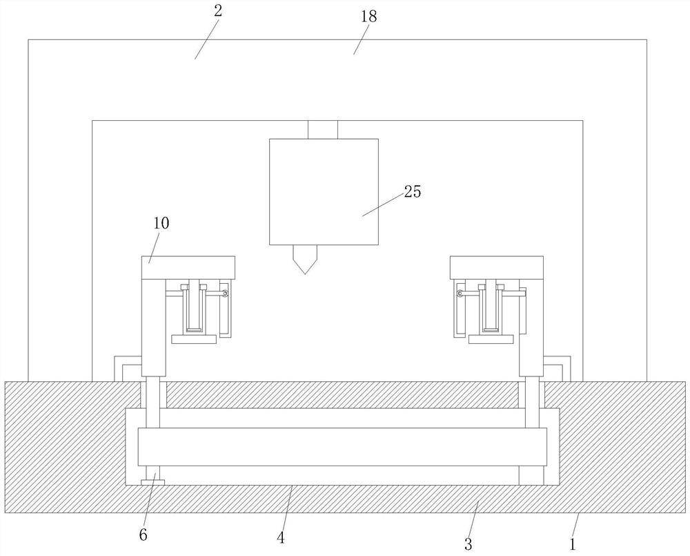
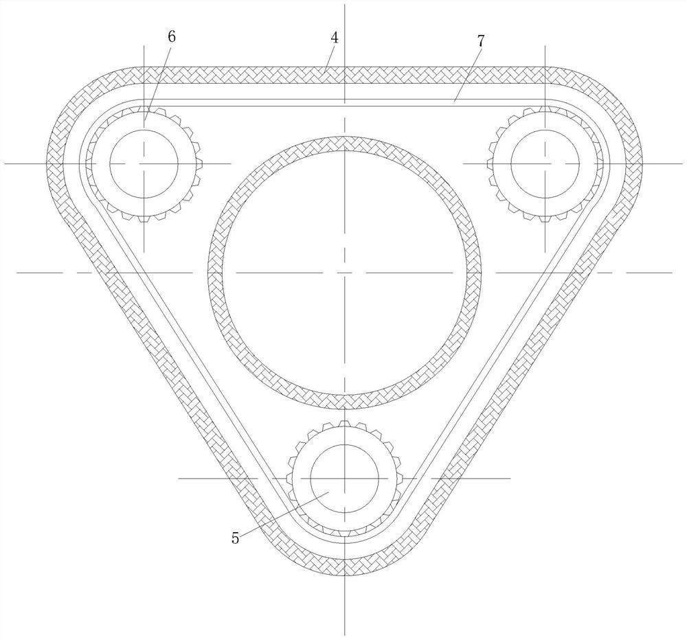
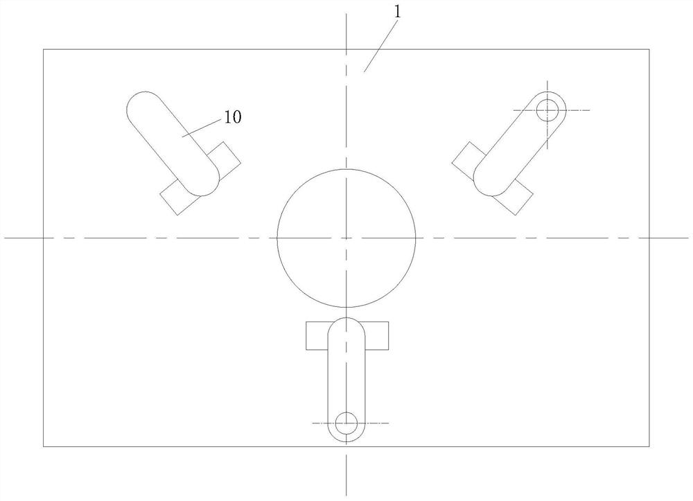
[0028] like Figure 1-Figure 7 As shown, a light steel structure processing punching device for house construction according to the present invention includes a positioning mechanism 1 and a punching mechanism 2. The top of the positioning mechanism 1 is fixedly equipped with a punching mechanism 2, and the positioning mechanism 1 includes a workbench 3, a drive box 4 is fixedly installed inside the workbench 3, and three vertical plates 9 are fixedly installed on the top of the workbench 3, and the output shaft of the drive box 4 extends to the inside of the riser 9 ;

[0029] The punching mechanism 2 includes a bracket 18, the inside of the bracket 18 is provided with a drive chamber 19, the inner wall of the drive chamber 19 is fixedly mounted...


PUM


Abstract

The invention relates to the field of steel structure punching, in particular to a machining and punching device for a lightweight steel structure for house construction. The machining and punching device comprises a positioning mechanism and a punching mechanism, the punching mechanism is fixedly arranged at the top of the positioning mechanism, the positioning mechanism comprises a workbench, and a driving box is fixedly arranged in the workbench. According to the machining and punching device, by arranging the positioning mechanism, a gear motor is used for driving two driven gears to synchronously rotate through a transmission chain belt, a gear vertical bar is promoted to drive a transmission toothed bar to rotate through a gear cross bar, so that three positioning plates gradually conduct positioning and clamping work on a to-be-punched workpiece located on the workbench, in addition, the whole clamping operation adopts mechanical operation, so that a manual clamping mode is avoided, the positioning effect and the positioning efficiency of the to-be-punched workpiece are remarkably improved, moreover, the tedious steps of manual clamping are simplified, so that the working time of workers is shortened, the labor intensity of the workers is lowered, and the punching precision of subsequent machining is guaranteed.

Description

technical field [0001] The invention relates to the field of steel structure punching, in particular to a light steel structure processing punching device for building construction. Background technique [0002] Steel is an iron-carbon alloy with a carbon content between 0.0218% and 2.11%. In order to ensure its toughness and plasticity, the carbon content generally does not exceed 1.7%. Steel has the advantages of high hardness and high strength, and is widely used in various fields; Steel structure is a structure composed of steel materials, which is one of the main types of building structures. The structure is mainly composed of beam steel, steel column, steel truss and other components made of section steel and steel plate, and adopts rust removal and antirust processes such as silanization, pure manganese phosphating, washing and drying, and galvanizing. The components or components are usually connected by welds, bolts or rivets. Because of its light weight and easy...

Claims


Application Information

Patent Timeline
Patent Type & Authority Applications(China)
IPC IPC(8): B23B41/00B23Q3/06B23Q11/08
Inventor 成衡军高多安
Owner 湖南鸿云钢模科技有限公司
Why Eureka
Eureka Blog
Learn More