A power amplifier power supply voltage control method and system
A voltage control method and technology for a control system, applied in control/regulation systems, improving amplifiers to reduce temperature/power supply voltage changes, electrical components, etc., can solve problems such as large bus voltage fluctuations, reduce bus voltage fluctuations, reduce Small energy storage capacitor, the effect of improving performance
- Summary
- Abstract
- Description
- Claims
- Application Information
AI Technical Summary
Problems solved by technology
Method used
Image
Examples
Embodiment 1
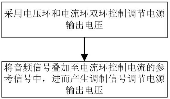
[0038] In Embodiment 1, a power amplifier power supply voltage control method specifically includes the following steps:
[0039] S01: Use voltage loop and current loop dual-loop control to adjust the output voltage of the power supply; specifically, the voltage loop is the outer loop, and the current loop is the inner loop. The error signal obtained by the proportional integral adjustment can be used as the given current signal of the current loop, and the difference between the given current signal and the real-time output current signal of the power supply can be used to obtain the error signal used to generate the modulation signal, and then adjust the output voltage of the power supply.
[0040] S02: superimpose the audio signal to the reference signal of the current loop control current, and then generate a modulation signal to adjust the output voltage of the power supply. Specifically, the power amplifier in this embodiment is specifically a Class D power amplifier, and ...
Embodiment 2
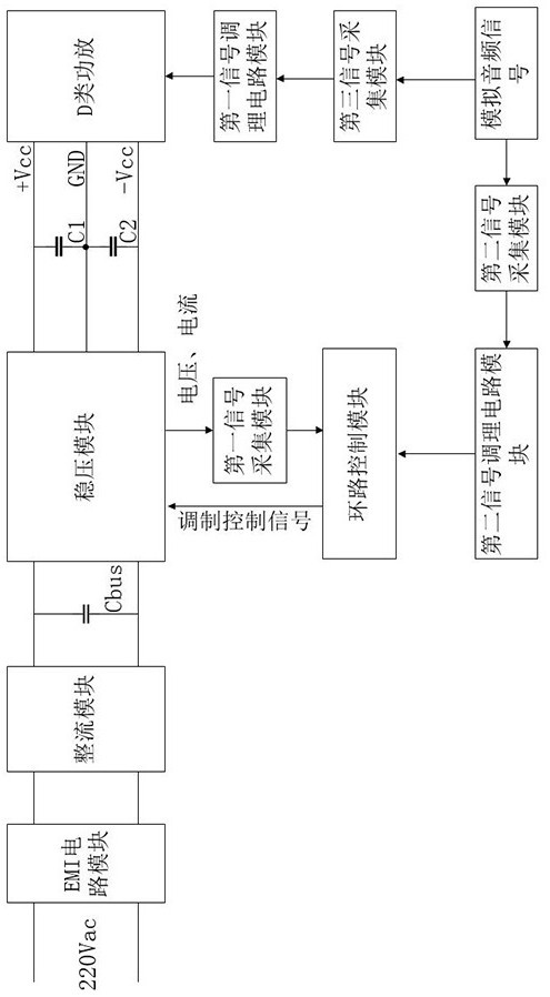
[0062] This embodiment has the same inventive concept as Embodiment 1. On the basis of Embodiment 1, a power amplifier power supply voltage control system is provided, such as image 3 As shown, the control system includes a loop control module, a voltage stabilizing module, a first signal acquisition module, and a second signal acquisition module. The first signal acquisition module is used to acquire the voltage signal and current signal of the voltage stabilizing module, and the second signal acquisition module It is used to collect the audio signal of the input power amplifier; the output end of the first signal acquisition module and the output end of the second signal acquisition module are connected to the loop control module, the output end of the loop control module is connected to the voltage stabilizing module, and the output end of the voltage stabilizing module is connected to the power amplifier , The first signal acquisition module is connected.
[0063] Specifi...
Embodiment 3
[0071] This embodiment has the same inventive concept as Embodiment 1. On the basis of Embodiment 1, a storage medium is provided, on which computer instructions are stored. When the computer instructions are running, a power amplifier power supply voltage control in Embodiment 1 is executed. method steps.
[0072] Based on this understanding, the technical solution of this embodiment is essentially or the part that contributes to the prior art or the part of the technical solution can be embodied in the form of a software product, and the computer software product is stored in a storage medium. Several instructions are included to make a computer device (which may be a personal computer, a server, or a network device, etc.) execute all or part of the steps of the methods in various embodiments of the present invention. The aforementioned storage medium includes: U disk, mobile hard disk, read-only memory (Read-Only Memory, ROM), random access memory (Random Access Memory, RAM...
PUM
 Abstract
Description
Claims
Application Information
 - R&D
- Intellectual Property
- Life Sciences
- Materials
- Tech Scout
- Unparalleled Data Quality
- Higher Quality Content
- 60% Fewer Hallucinations
Browse by: Latest US Patents, China's latest patents, Technical Efficacy Thesaurus, Application Domain, Technology Topic, Popular Technical Reports.
© 2025 PatSnap. All rights reserved.Legal|Privacy policy|Modern Slavery Act Transparency Statement|Sitemap|About US| Contact US: help@patsnap.com


