
Hydraulic pressure relief device and method

An equipment and pressure relief technology, applied in the field of hydraulic control, can solve the problem of hydraulic actuator load relief, achieve smooth pressure relief, ensure pressure relief efficiency, and protect equipment and operators.

Active Publication Date: 2021-04-16
SHANDONG TAIFENG INTELLIGENT CONTROL CO LTD
View PDF8 Cites 0 Cited by
  • Summary
  • Abstract
  • Description
  • Claims
  • Application Information

AI Technical Summary

Problems solved by technology

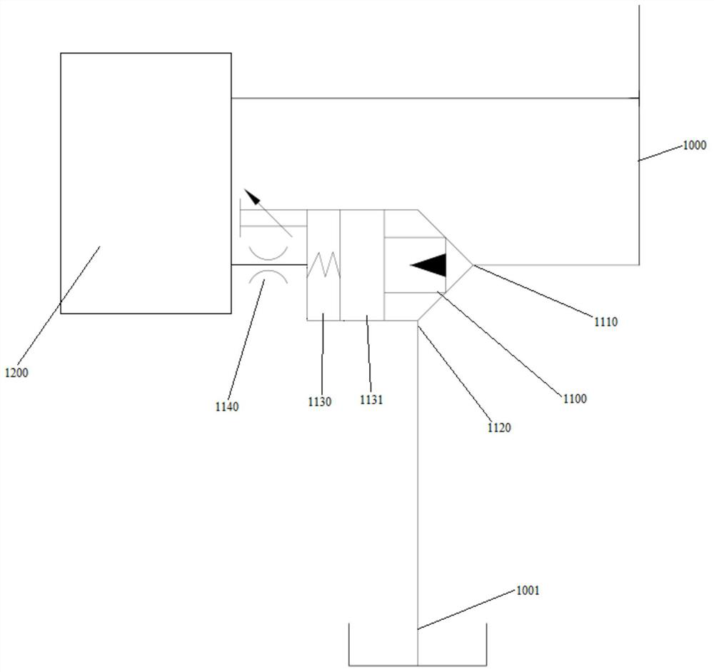
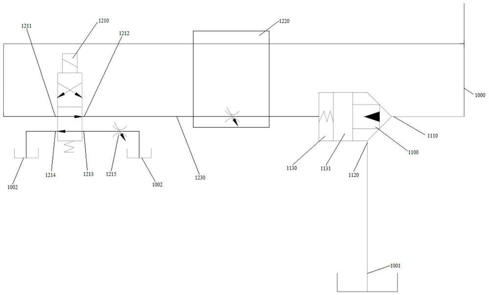
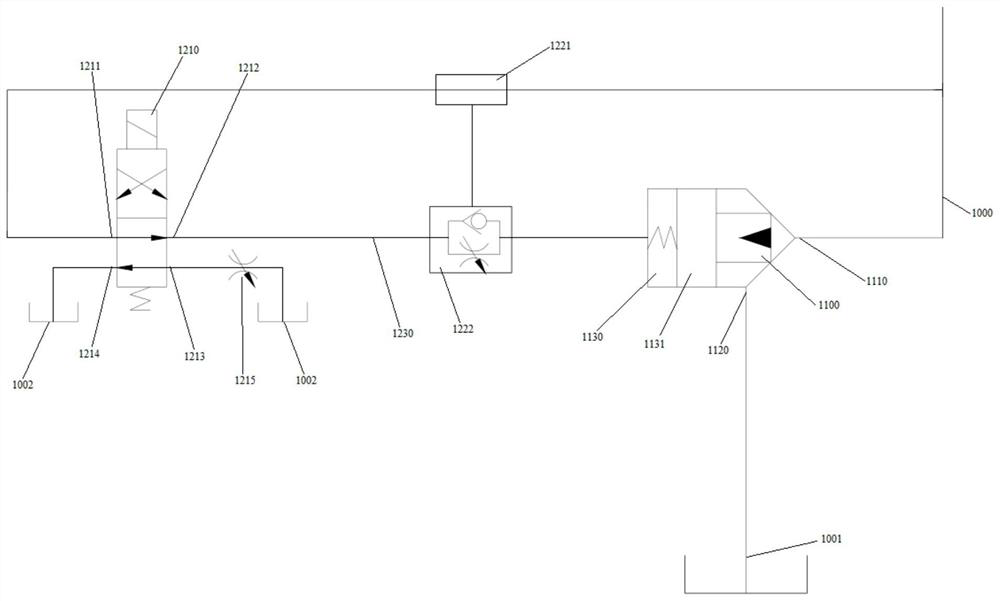
[0003] In view of this, the purpose of one or more embodiments of this specification is to propose a hydraulic pressure relief device and method to solve the problem of hydraulic actuators under high frequency and high pressure. The problem of leaking task switching

Method used


Image

  • Hydraulic pressure relief device and method
  • Hydraulic pressure relief device and method
  • Hydraulic pressure relief device and method

Examples


Embodiment Construction

[0044] In order to make the purpose, technical solutions and advantages of this specification more clear, the following will further describe this specification in detail in combination with specific embodiments and with reference to the accompanying drawings.

[0045] It should be noted that, unless otherwise defined, the technical terms or scientific terms used in the embodiments of the present specification shall have ordinary meanings understood by those skilled in the art to which the present disclosure belongs. "First", "second" and similar words used in the present disclosure do not indicate any order, quantity or importance, but are only used to distinguish different components. "Comprising" or "comprising" and similar words mean that the elements, objects or method steps appearing before the word cover the elements, objects or method steps listed after the word and their equivalents, without excluding other elements, objects or method steps. Method steps. Words such ...


PUM


Abstract

One or more embodiments of the invention provide a hydraulic pressure relief device and method. The hydraulic pressure relief device comprises a cartridge valve and a control unit; the cartridge valve is arranged on an oil pipe connected with an oil tank; the cartridge valve is provided with an oil inlet, an oil outlet and a control cavity; a control piston capable of sliding is arranged in the control cavity, and the control cavity is connected with the control unit; and the control unit is configured to detect the pressure intensity of fluid in the oil pipe through connection with the oil pipe so as to control sliding of the control piston in the control cavity and control a communication state of the oil inlet and the oil outlet. One or more embodiments of the invention detect the fluid pressure in the oil pipe through the control unit, control the communication state of the oil pipe through the cartridge valve according to the pressure, reduce an opening of the oil pipe flowing to the oil tank when the fluid pressure in the oil pipe is high, release pressure stably, increase the opening of the oil pipe flowing to the oil tank after the fluid pressure in the oil pipe is reduced, and release pressure quickly, therefore, the pressure relief efficiency is ensured while the device and operators are protected, and the effects of increasing the speed and efficiency are achieved.

Description

technical field [0001] One or more embodiments of this specification relate to the technical field of hydraulic control, and in particular to a hydraulic pressure relief device and method. Background technique [0002] With the rapid development of social production level and the development of hydraulic forging equipment, the production speed and efficiency of hydraulic forging equipment have become a hot research direction. However, while the speed of the equipment is increasing, a new problem is exposed to everyone. Various hydraulic actuators operate under high frequency and high pressure, and the problem of load leakage when the equipment performs one action and turns to the next action has become a new concern. point. If the load is not released and the next process is carried out directly, the moment the high-pressure valve is directly opened will generate huge vibration and impact, which will have a great impact on the life of the equipment, the production of the wo...

Claims


Application Information

Patent Timeline
IPC IPC(8): F15B13/02F15B21/00F15B19/00
Inventor 王振华杨存强王景海李强
Owner SHANDONG TAIFENG INTELLIGENT CONTROL CO LTD
Learn More