
Moving frame special for power equipment

A technology of electric equipment and mobile racks, which is applied to lifting equipment braking devices, portable lifting devices, and trolley cranes. The effect of labor intensity

Inactive Publication Date: 2021-04-16
无锡市雨峰汽轮机配件厂
View PDF0 Cites 0 Cited by
  • Summary
  • Abstract
  • Description
  • Claims
  • Application Information

AI Technical Summary

Problems solved by technology

[0002] Electric hoists are not overhauled for electrical equipment, hydraulic pumps and motors are replaced, and the pumps weigh about 100 catties and the motors are 1,000 kg. There are potential safety hazards and the replacement time is long

Method used


Image

  • Moving frame special for power equipment
  • Moving frame special for power equipment
  • Moving frame special for power equipment

Examples


Embodiment Construction

[0016]Next, the technical solutions in the embodiments of the present invention will be apparent from the embodiment of the present invention, and it is clearly described, and it is understood that the described embodiments are merely embodiments of the present invention, not all of the embodiments. Based on the embodiments of the present invention, there are all other embodiments obtained without making creative labor without making creative labor premises.

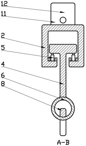
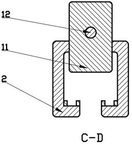
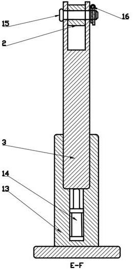
[0017]Such asFigure 1-4As shown, the present invention provides a power frame for a power device, including a fixed shaft 1, and the fixed shaft 1 is hinged to one end of the connecting beam 2, and the other end of the connecting beam 2 is hingedly coupled with a second fixing shaft 3, said A T-shaped block 4 is connected inside the connecting beam 2, and the T-shaped block 4 is provided with a pair of rollers 5, the roller 5 on the inner wall of the connecting beam 2, the T-shaped block 4 projecting out the connecting beam 2 is ...


PUM


Abstract

The invention discloses a moving frame special for power equipment, and relates to the technical field of metallurgy. The moving frame comprises a fixing shaft, the fixing shaft is hinged with one end of a connecting beam, the other end of the connecting beam is hinged with a second fixing shaft, a T-shaped block is connected with the interior of the connecting beam, a pair of rolling wheels is arranged at the bottom of the T-shaped block, the rolling wheels are arranged on the inner wall of the connecting beam, the T-shaped block extends out of the connecting beam and is connected with a fixing circular ring, the fixing circular ring is connected with an upper hook of a hand-drive block, the hand-drive block is provided with a lower hook and a pull rope, a limiting block is arranged above the connecting beam, and the limiting block penetrates through a connecting groove in the connecting beam to arrive at the interior of the connecting beam. According to the moving frame, a hydraulic pump and a motor are pulled up through the pull rope on the hand-drive block, and the heights of the fixing shaft and the second fixing shaft are unbalanced by starting the hydraulic rod, so that the T-shaped block drives the hand-drive block to move towards the lower fixing shaft through the rolling wheels, and the hand-drive block stops at a designated position through the limiting block.

Description

Technical field[0001]The present invention relates to the field of metallurgical technology, and more particularly to a power frame for a power device.Background technique[0002]Power equipment does not check the electric hoist, replace the hydraulic pump and motor, use the people to carry a single weight of 100 kg, the motor is 1000kg, there is a safety hazard, and the replacement time is longer.Inventive content[0003]In order to overcome the above-described drawbacks of the prior art, the present invention provides a mobile phone for a power device. When used, pull the hydraulic pump and motor by the manual gourd, by starting the hydraulic rod, so that the fixed axis and second fixation The axis is unbalanced, thereby driving the T-shaped block to move the manual hoist to move the shaft to a lower side, and the limit shaft is pre-extracted, so that the limit block is moved to the T-shaped block limit in the connecting beam, pull out the movement You can start after manual gourd, do...

Claims


Application Information

Patent Timeline
IPC IPC(8): B66C19/00B66C5/02B66C9/08B66C11/00B66C13/08B66D3/16
Inventor 平春明
Owner 无锡市雨峰汽轮机配件厂
Learn More