Material overturning and conveying device of short material sawing and drilling all-in-one machine

A technology of conveying device and integrated machine, which is applied in the direction of conveyor objects, transportation and packaging, metal processing, etc., and can solve the problems of inapplicability and inability to adapt to bars of different diameters

Pending Publication Date: 2021-04-16
SUZHOU KINKALTECK MACHINERY TECH
View PDF0 Cites 0 Cited by
  • Summary
  • Abstract
  • Description
  • Claims
  • Application Information

AI Technical Summary

Problems solved by technology

[0002] The bar needs to be sawed into short pieces by sawing machine, and then the next step of end face drilling operation, and the sawing machine generally needs to transport the bar to the sawing machine through the feeding device for sawing, but currently The feeding device generally includes a material frame, and then the bar is placed in the material frame, and then a bar is lifted to a whole material platform by the jacking mechanism, and then the bar is lifted by the jacking mechanism Lift it to the longitudinal conveying device, and convey the bar to the sawing head of the sawing machine through the longitudinal conveying device for sawing. However, there is a shortcoming in the current feeding device: due to the limitation of the jacking mechanism and the monolithic platform , the jacking mechanism is not suitable for bars of different diameters, especially when the diameter changes greatly, since the jacking mechanism needs to selectively lift a bar, the structure of the jacking mechanism is very targeted, and it can only It is suitable for lifting the rods of a certain specification. When the diameter of the rods changes greatly, this kind of lifting mechanism and monolithic platform cannot be applied

Method used


Image

  • Material overturning and conveying device of short material sawing and drilling all-in-one machine
  • Material overturning and conveying device of short material sawing and drilling all-in-one machine
  • Material overturning and conveying device of short material sawing and drilling all-in-one machine

Examples


Embodiment Construction

[0025] The present invention will be described in further detail below through specific examples.

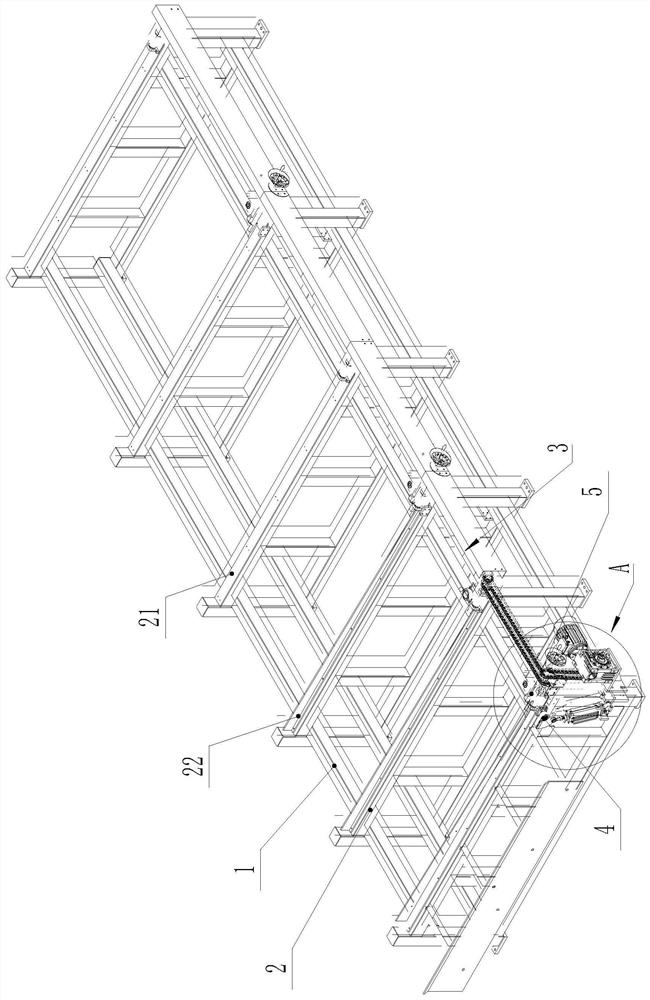
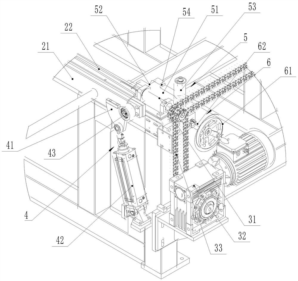
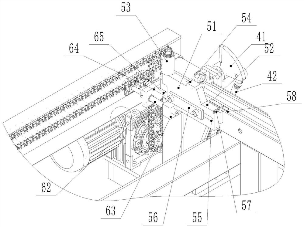
[0026] Such as Figure 1 to Figure 3 As shown, a material turning and conveying device of a short material sawing, cutting and drilling integrated machine includes a frame 1, and the frame 1 is provided with several supporting beams 2 for placing bars, and the supporting beams 2 The upper end of the upper end is provided with an inclined guide support surface that is convenient for bar rolling; in this embodiment, the support beam 2 includes a beam body 21 and a guide support plate 22, and the guide support plate 22 is detachably fixed on the beam body 21. The guide support surface is arranged on the guide support plate 22, and the guide support surface is T-shaped in cross section. By replacing the guide support plate 22, the guide support surface with different inclinations can be adjusted to meet the needs of bars of different sizes. Orientation requirements.

[0027]The lo...


PUM


Abstract

The invention discloses a material overturning and conveying device of a short material sawing and drilling all-in-one machine. The machine comprises a rack, a plurality of support cross beams for placing bars are arranged on the rack, and inclined guide support surfaces for facilitating rolling of the bars are arranged at the upper ends of the support cross beams; the support cross beams are arranged on the lower side of the guide support faces to form transverse discharging sides, a longitudinal conveying device is arranged on a transverse discharging side of the rack, limiting blocking mechanisms are transversely installed on at least two support cross beams in a sliding mode, transverse adjusting mechanisms for adjusting the transverse positions of the limiting blocking mechanisms are arranged on the rack, each limiting and blocking mechanism is provided with an inner blocking structure used for blocking the bars on the support cross beams and an outer positioning structure used for positioning the bars to fall onto the longitudinal conveying device, and the support cross beams are further provided with a material overturning mechanism used for overturning and conveying the bars on the guide support faces to the longitudinal conveying device one by one. The material overturning and conveying device can be suitable for automatic feeding of bars with different diameters, and the automatic feeding requirement of the sawing and drilling all-in-one machine is met.

Description

technical field [0001] The invention relates to a material turning and conveying device, in particular to a material turning and conveying device on a short material sawing, cutting and drilling integrated machine. Background technique [0002] The bar needs to be sawed into short pieces by sawing machine, and then the next step of end face drilling operation, and the sawing machine generally needs to transport the bar to the sawing machine through the feeding device for sawing, but currently The feeding device generally includes a material frame, and then the bar is placed in the material frame, and then a bar is lifted to a whole material platform by the jacking mechanism, and then the bar is lifted by the jacking mechanism Lift it to the longitudinal conveying device, and convey the bar to the sawing head of the sawing machine through the longitudinal conveying device for sawing. However, there is a shortcoming in the current feeding device: due to the limitation of the j...

Claims


Application Information

Patent Timeline
Patent Type & Authority Applications(China)
IPC IPC(8): B65G47/248B65G47/88B65G13/07B23Q7/00
Inventor 柯晓华
Owner SUZHOU KINKALTECK MACHINERY TECH
Why Eureka
Try Eureka