
High-precision grinding machine for optical test detection

A high-precision, optical technology, used in optical surface grinders, grinding machine tools, preparation of samples for testing, etc., can solve the problems of detection surface contamination, influence detection surface accuracy, influence test detection accuracy, etc., to ensure accuracy and cleanliness degree, ensure the uniformity of grinding, and the effect of convenient use

Active Publication Date: 2021-04-16
天津和顺云科技有限公司 +1
View PDF7 Cites 0 Cited by
  • Summary
  • Abstract
  • Description
  • Claims
  • Application Information

AI Technical Summary

Problems solved by technology

[0003] However, for the existing testing mills, the loading and unloading of the optical elements is mostly carried out directly by hand, so it is unavoidable that the contact between the human hand and the detection surface will occur during the loading and unloading process, especially for the For optical components that are small and require high precision, direct contact with human hands can easily cause contamination of the detection surface, and even affect the accuracy of the detection surface, thereby affecting the accuracy of test detection

Method used


Image

  • High-precision grinding machine for optical test detection
  • High-precision grinding machine for optical test detection
  • High-precision grinding machine for optical test detection

Examples


Embodiment Construction

[0029] The following will clearly and completely describe the technical solutions in the embodiments of the present invention with reference to the accompanying drawings in the embodiments of the present invention. Obviously, the described embodiments are only some, not all, embodiments of the present invention. Based on the embodiments of the present invention, all other embodiments obtained by persons of ordinary skill in the art without making creative efforts belong to the protection scope of the present invention.

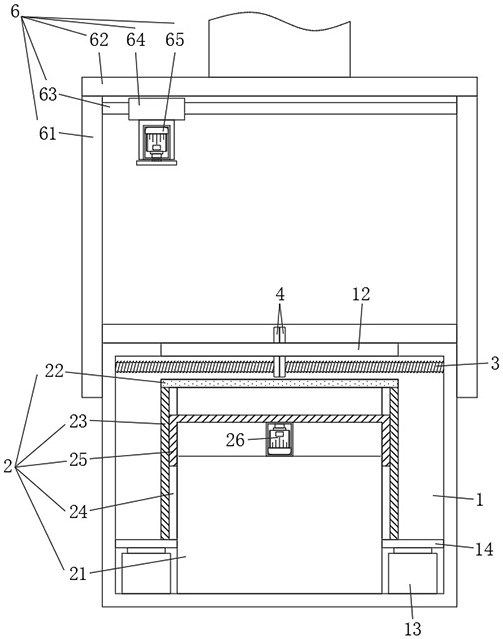
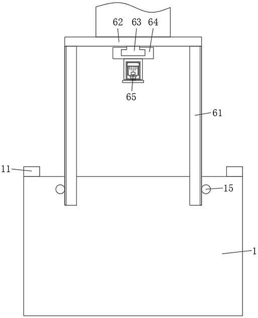
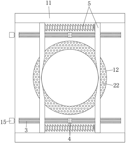
[0030] see Figure 1-Figure 5 As shown, the present invention provides a kind of high-precision grinding machine for optical test detection, mainly comprising:

[0031] The grinding table 1 is equipped with a negative suction fixing assembly 2 at the middle position of the grinding table 1, and rotatable screw rods 3 are arranged on both sides of the negative suction fixing assembly 2, and each screw rod 3 is sleeved with a two moving plates 4;

[0032] The ...


PUM


Abstract

The invention belongs to the technical field of optical test equipment, and discloses a high-precision grinding machine for optical test detection. The high-precision grinding machine comprises a grinding table, a material clamping assembly and a liftable grinding assembly, wherein a negative suction fixing assembly is installed in the middle of the grinding table, rotatable screw rods are arranged on both sides of the negative suction fixing assembly, and two moving plates sleeve each screw rod; the material clamping assembly is detachably placed at the top of the grinding table, and the material clamping assembly comprises two symmetrical clamping plates and two clamping springs symmetrically connected between the two clamping plates; when the material clamping assembly is placed at the top of the grinding table, the clamping plates are perpendicular to the lead screws, and the two movable plates are limited between the two clamping plates; and when the grinding assembly descends, the two lead screws are driven to rotate synchronously. In conclusion, based on the arrangement of the material clamping assembly, direct contact with the element detection surface in the feeding and discharging process can be effectively avoided, and therefore the precision and the cleanliness degree of the detection surface obtained after accurate grinding are guaranteed to the maximum extent.

Description

technical field [0001] The invention belongs to the technical field of optical test equipment, and in particular relates to a high-precision grinding machine for optical test detection. Background technique [0002] Specifically, when performing performance testing of optical components such as glass and metal (for example: metallographic testing of metals, surface element testing of glass), it is necessary to polish the testing surface of the optical components to the required accuracy, and thus it is necessary to use the corresponding mill. [0003] However, for the existing testing mills, the loading and unloading of the optical elements is mostly carried out directly by hand, so it is unavoidable that the contact between the human hand and the detection surface will occur during the loading and unloading process, especially for the For optical components that are small and require high precision, direct contact with human hands can easily cause contamination of the dete...

Claims


Application Information

Patent Timeline
Patent Type & Authority Applications(China)
IPC IPC(8): B24B13/00B24B37/00B24B37/11B24B37/27B24B37/34B24B47/20B24B47/22G01N1/28
Inventor 周健
Owner 天津和顺云科技有限公司
Learn More