Dust collection structure for hardware building material construction and perforating device of dust collection structure

A technology for punching devices and building materials, applied in positioning devices, metal processing equipment, metal processing machinery parts, etc., can solve the problems of affecting the dust collection effect, poor dust removal effect, and inability to remove dust, etc., to achieve good dust collection effect, Effect of reducing dust and reducing dust adhesion

Inactive Publication Date: 2021-04-16
马鞍山天哲环保科技有限公司
View PDF0 Cites 0 Cited by
  • Summary
  • Abstract
  • Description
  • Claims
  • Application Information

AI Technical Summary

Problems solved by technology

[0005] The purpose of the present invention is to provide a dust suction structure for hardware and building materials construction and its punching device, which solves the problem of covering and sweeping dust suction operations through the vacuum cleaner, and the degree of fit is not high, which affects the dust suction effect. When working, there will be a lot of slight particles adsorbed on the working surface, and the dust absorbed on the working surface cannot be removed directly through the vacuum cleaner operation, resulting in a technical problem of poor dust removal effect

Method used


Image

  • Dust collection structure for hardware building material construction and perforating device of dust collection structure
  • Dust collection structure for hardware building material construction and perforating device of dust collection structure
  • Dust collection structure for hardware building material construction and perforating device of dust collection structure

Examples


Embodiment Construction

[0030] The technical solutions of the present invention will be clearly and completely described below in conjunction with the embodiments. Apparently, the described embodiments are only some of the embodiments of the present invention, not all of them. Based on the embodiments of the present invention, all other embodiments obtained by persons of ordinary skill in the art without creative efforts fall within the protection scope of the present invention.

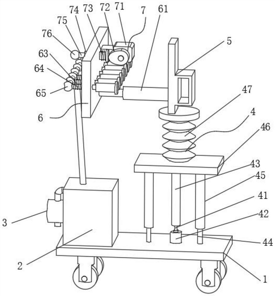
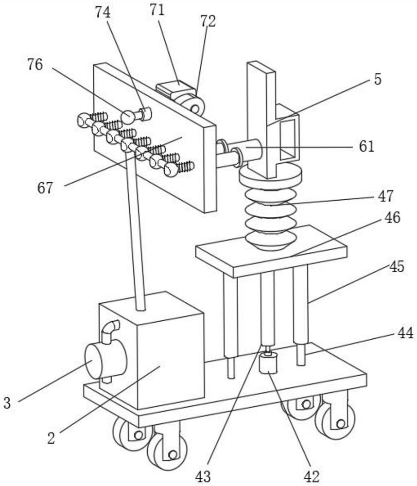
[0031] Such as Figure 1-5 As shown, a dust collection structure for hardware and building materials construction, including: body 1, dust collection box 2, emptying machine 3, lifting structure 4, handle 5, dust suction structure 6 and vibration structure 7, the top side of the body 1 is installed There is a dust collection box 2, an emptying machine 3 is installed on the side wall of the dust collection box 2 through bolts, a lifting structure 4 is installed side by side on the dust collection box 2, and a handle 5 is ins...


PUM


Abstract

The invention discloses a dust collection structure for hardware building material construction and a perforating device of the dust collection structure. The dust collection structure comprises a vehicle body, a dust collection box, an emptying machine, a lifting structure, a handle, a dust collection structure body and a vibration structure, the dust collection box is installed on the top side of the vehicle body, and the emptying machine is installed on the side wall of the dust collection box through bolts in a matched mode; and the lifting structure is installed on one side of the dust collection box side by side, the dust collection structure is installed on the handle, the vibration structure is installed on the dust collection structure side by side, and through the arrangement of the dust collection structure and cooperative operation of a first air cylinder, a fixing plate is pushed through a first pneumatic rod, an air bag is attached to hardware, and multi-point cooperative extrusion can be achieved in a matched mode, various bent planes can be attached, a better dust collection effect can be achieved, during fixed-point dust collection, the better dust collection effect can be achieved by rotating a positioning nut, changing the arrangement radian of the air bags and arranging the multiple air bags along the working face, flying dust on a construction face is reduced, and a better dust collection effect is achieved.

Description

technical field [0001] The invention relates to the technical field of hardware and building materials construction, in particular to a dust suction structure and a punching device for hardware and building materials construction. Background technique [0002] Hardware and building materials refer to the five metal materials of gold, silver, copper, iron, and tin. Hardware and building materials are the mother of industry; the foundation of national defense, and the products of hardware and building materials are usually only divided into two categories: large hardware and small hardware. DaWuJin building materials refer to steel plates, steel bars, flat irons, universal angle steels, channel irons, I-shaped irons and various types of steel materials. [0003] In the construction of hardware and building materials, a large amount of dust will be generated. The existing dust collection device can only use the vacuum cleaner to perform sweeping and dust collection operations. ...

Claims


Application Information

Patent Timeline
IPC IPC(8): B23B47/00B23Q3/00B08B5/04B08B13/00B23Q11/00
Inventor 刘宪文游登洲沈玉鹏刘成
Owner 马鞍山天哲环保科技有限公司
Why Eureka
Try Eureka