Eureka AIR delivers breakthrough ideas for toughest innovation challenges, trusted by R&D personnel around the world.

Solar power generation panel cleaning device and cleaning method thereof

A technology for a solar power generation panel and a cleaning device, applied in the field of cleaning devices and solar power generation, can solve the problems of damage to the layer, cracks, and high cleaning costs, and achieve the effects of improving the degree of cleaning, improving the elasticity, and improving the cleaning ability.

Active Publication Date: 2021-04-16
北京新奥京谷燃气有限公司
View PDF7 Cites 1 Cited by
  • Summary
  • Abstract
  • Description
  • Claims
  • Application Information

AI Technical Summary

Problems solved by technology

Because the silicon wafer in the middle of the photovoltaic panel is very fragile, it is likely to cause cracks due to gravity
Avoid cleaning during the peak period of power generation. When the photovoltaic system is operating efficiently at noon in summer, the surface temperature of photovoltaic panels is very high due to exposure to sunlight. The principle is that the material inside the photovoltaic panel will undergo irreversible changes, which will cause damage to the solar power generation panel. Avoid using sharp objects to wipe the glass surface, which will not only damage the surface layer, but also affect the diffusion of light
Affect power generation efficiency
[0004] In the prior art, the cleaning device of some semi-automatic cleaning equipment is not ideal when it is working. Since the surface of the solar power generation panel is easy to scratch, several times of cleaning will cause irreversible damage to the solar power generation panel, making the solar power generation panel transparent. The light rate is weakened, and the photoelectric conversion efficiency is greatly reduced
Moreover, the current cleaning method is highly dependent on water resources. In some western regions, where water resources are scarce, the cleaning cost will be very high.

Method used


Image

  • Solar power generation panel cleaning device and cleaning method thereof
  • Solar power generation panel cleaning device and cleaning method thereof
  • Solar power generation panel cleaning device and cleaning method thereof

Examples


Embodiment Construction

[0032] The following will clearly and completely describe the technical solutions in the embodiments of the present invention with reference to the accompanying drawings in the embodiments of the present invention. Obviously, the described embodiments are only some, not all, embodiments of the present invention. Based on the embodiments of the present invention, all other embodiments obtained by persons of ordinary skill in the art without making creative efforts belong to the protection scope of the present invention.

[0033] In the following description, many specific details are set forth in order to fully understand the present invention, but the present invention can also be implemented in other ways different from those described here, therefore, the protection scope of the present invention is not limited by the specific implementation disclosed below. Example limitations.

[0034] In describing the present invention, it should be understood that the terms "center", "l...


PUM


Abstract

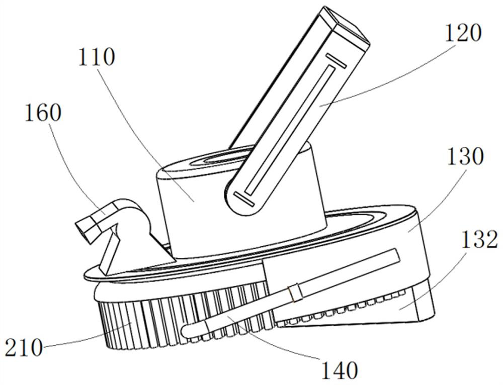
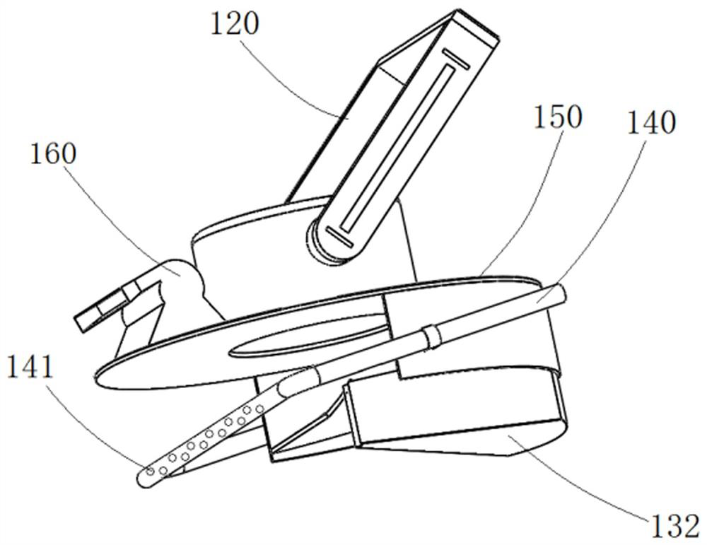
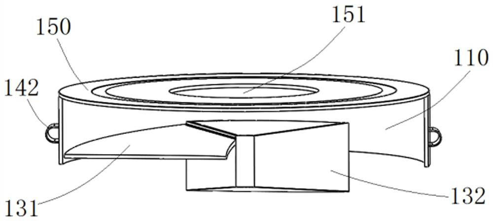
The invention discloses a solar power generation panel cleaning device and a cleaning method thereof. The solar power generation panel cleaning device comprises a cleaning assembly and an air blowing device which are connected together through an installation shell, matching holes are formed in the circumferential side face of the installation shell and connected with an assembly frame, a circumferential baffle and an upper baffle are arranged at the lower part of the installation shell, an opening is formed in the front part of the circumferential baffle, a spiral blade is arranged on the inner side face of the circumferential baffle and spirally ascends from the opening, and one side of the spiral blade is connected with a dust collection box which is arranged on the inner side face of the circumferential baffle, the air blowing device is arranged at the front part of the upper baffle, an air blowing opening is formed in the front end of the air blowing device, a driving motor is fixedly connected into the installation shell and connected with a lower rotating brush, bristles are arranged at the bottom of the rotating brush, and a water seepage pipe is arranged between the bristles and installed on the outer side face of the circumferential baffle through a connecting piece. A solar power generation panel is cleaned by rotating the bristles, so that the surface of the solar power generation panel is prevented from being scratched, and the solar power generation panel always keeps higher light transmittance.

Description

technical field [0001] The invention relates to the fields of solar power generation and cleaning devices, in particular to a solar power generation panel cleaning device and a cleaning method thereof. Background technique [0002] Solar panels, also known as solar cell modules, are photoelectric semiconductor sheets that use sunlight to generate electricity directly. Several solar cells are assembled on a board in a certain way. It is the core part of the solar power generation system. There are two ways of solar power generation, one is light-heat-electricity conversion, and the other is light-electricity direct conversion. The light-heat-electricity conversion method uses the thermal energy generated by solar radiation to generate electricity. Generally, the solar collector converts the absorbed heat energy into working medium vapor, and then drives a steam turbine to generate electricity. The former process is a light-to-heat conversion process; the latter process is a ...

Claims


Application Information

Patent Timeline
Patent Type & Authority Applications(China)
IPC IPC(8): B08B1/04B08B1/00B08B5/02B08B13/00H02S40/10
CPCY02E10/50
Inventor 卢倩赵姗姗
Owner 北京新奥京谷燃气有限公司
Why Eureka
Eureka Blog
Learn More