For device for the dust removal of the turntable gas

A gas dust removal and converter technology, which is applied in the field of devices for dust removal of converter gas, can solve problems such as speed peaks, damage filter elements, shorten filter life, etc., and achieve the effects of reducing explosion risk and reducing wear and tear.

Active Publication Date: 2022-08-05
PRIMETALS TECH AUSTRIA GMBH
View PDF6 Cites 0 Cited by
  • Summary
  • Abstract
  • Description
  • Claims
  • Application Information

AI Technical Summary

Problems solved by technology

[0012] However, for filters with ceramic filter elements, there is also the problem that velocity peaks can occur when the converter gas flows into the housing, which can damage the filter element
In addition, such velocity peaks can lead to turbulence in the funnel-shaped region of the housing below the inflow opening, whereby the dust that has been separated and deposited there is kicked up again and this previously separated The dust has to be separated by passing through the filter element again or this dust additionally loads the filter element by abrasion and can shorten the service life of the filter

Method used


Image

  • For device for the dust removal of the turntable gas
  • For device for the dust removal of the turntable gas
  • For device for the dust removal of the turntable gas

Examples


Embodiment Construction

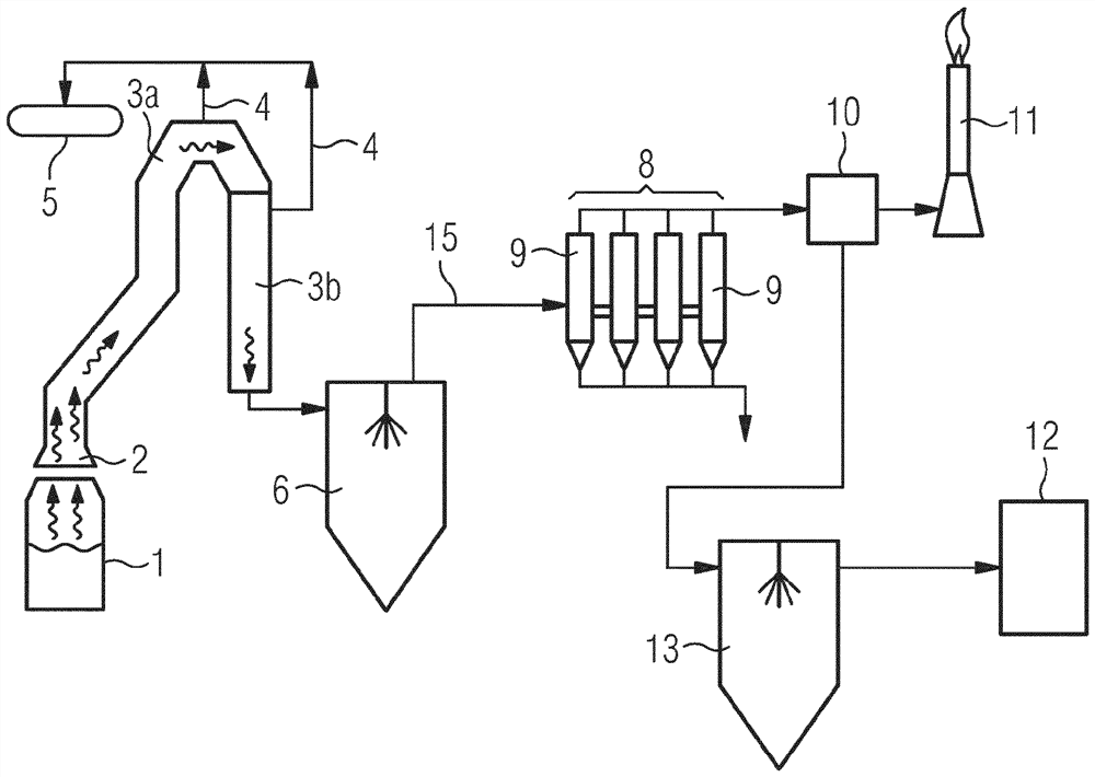
[0053] figure 1 One possible plant for the treatment of converter gases is shown and the basic sequence is explained. The device according to the invention replaces the figure 1 The device 8 for dedusting shown in is installed.

[0054] exist figure 1The converter gas rises from the converter 1 into the hood 2, which is shown by the corrugated arrows. By means of the hood, in the case shown, the converter gases are conducted with steam generation into the cooling chimney, which is the first cooling device for indirect cooling. The cooling chimney includes cooling chimney pieces 3a and 3b. The steam produced by the heat exchange between the converter gas and the cooling medium water guided in pipes not shown in the cooling chimney is led to the steam drum 5 via the pipe 4 . In the cooling stack, a first cooling step is carried out for the converter gas by means of indirect cooling by means of water / steam. At the end of the cooling chimney 3a, the converter gas has a tempe...


PUM


Abstract

The invention relates to a device ( 8 ) for dedusting converter gases, comprising at least one housing ( 9 ) with a circular cross-section, in which housing one or more devices capable of being removed from the converter are arranged Filter elements ( 18 ) through which gas flows, each housing having at least one feed line ( 15 ) for converter gas into the housing, wherein the feed line is opposite to the housing The operating state of the body opens into the housing ( 9 ) below the filter element ( 18 ) in such a way that a largely radial flow initially forms in the housing. In order to reduce the velocity peaks when the converter gas flows into the housing, provision is made here for the feed line ( 15 ) to end at the housing ( 9 ) and to form an elongated inflow opening ( 16 ) there, The inflow port has a larger size in the circumferential direction of the casing (9) than in the height direction (17) of the casing, wherein the inside of the casing (9) is connected with the inflow port (16) inside. There are no flow-guiding internals between the filter elements (18).

Description

technical field [0001] The invention relates to a device for dedusting converter gases, comprising at least one housing with a circular cross-section, such as a cylindrical housing, in which one or more housings are arranged Filter elements through which the converter gas can flow through, each housing having at least one supply line for the converter gas which leads into the housing, wherein the supply line operates relative to the housing The state opens into the housing below the filter element in such a way that a largely radial flow initially forms in the housing. [0002] A “filter element” here means a mechanically filtered element through which a gas flows, wherein the dust contained in the gas is deposited on the filter element. For each housing, usually a plurality of filter elements, the upper and lower ends of the filter elements are usually in a horizontal plane, respectively. [0003] The feed line opens into the housing in such a way that the fluid flowing int...

Claims


Application Information

Patent Timeline
Patent Type & Authority Patents(China)
IPC IPC(8): B01D46/02
CPCB01D46/0041B01D46/02
Inventor A·弗莱钱德尔T·斯坦帕泽A·斯坦万特E·S·维默
Owner PRIMETALS TECH AUSTRIA GMBH
Why Eureka
Try Eureka