Device for removing dust from converter gas

A technology for gas dust removal and converter, which is applied in the field of devices for dust removal of converter gas, can solve problems such as speed peaks, damage filter elements, increase load, etc., and achieve the effects of improving compressive strength and simple structure

Active Publication Date: 2021-04-13
PRIMETALS TECH AUSTRIA GMBH
View PDF6 Cites 0 Cited by
  • Summary
  • Abstract
  • Description
  • Claims
  • Application Information

AI Technical Summary

Problems solved by technology

[0012] However, for filters with ceramic filter elements, there is also the problem that velocity peaks can occur when the converter gas flows into the housing, which can damage the filter element
In addition, such velocity peaks can lead to turbulence in the funnel-shaped region of the housing below the...

Method used


Image

  • Device for removing dust from converter gas
  • Device for removing dust from converter gas
  • Device for removing dust from converter gas

Examples


Embodiment Construction

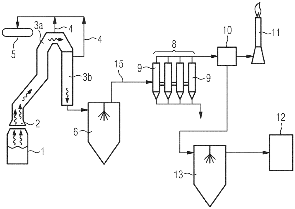
[0053]figure 1 A possible device for processing the converter gas is shown and the basic flow will be described. The apparatus according to the present invention is replacedfigure 1 The device 8 shown in the presence is mounted.

[0054]infigure 1 The medium transfer furnace gas rises from the converter 1 to the envelope 2, which is shown by a corrugated arrow. The converter gas is directed to the cooling chimney by the shield in the case where steam is generated, the cooling chimney is a first cooling device for performing indirect cooling. The cooling chimney includes a cooling of the smoke 3a and 3b. The steam generated between the heat exchange between the cooling medium water obtained by the converter gas and the tube of the cooled chimney is introduced is directed to the vapor 5 via the conduit 4. In the cooling chimney, the first cooling step is performed for the converter gas by indirect cooling by water / vapor. At the end of the cooling chimney member 3a, the converter gas ha...


PUM


Abstract

The invention relates to a device (8) for removing dust from converter gas, comprising at least one housing (9) having a round cross-section in which one or more filter elements (18) are arranged through which converter gas can flow, and, for each housing, at least one feed conduit (15) for feeding converter gas into the housing. Based on the operational state of the housing, the feed conduit opens into the housing (9) below the filter elements (18) in such a way that an initially largely radial flow forms in the housing. The aim of the invention is to reduce velocity peaks as the converter gas flows into the housing. This aim is achieved, according to the invention, in that the feed conduit (15) ends at the housing (9) and there forms an elongated inflow opening (16), which has a larger dimension in the circumferential direction of the housing (9) than in the height direction (17) of the housing. The interior of the housing (9) is free of flow-conducting fittings between the inflow opening (16) and the filter elements (18).

Description

Technical field[0001]The present invention relates to a means for supplying a converter gas dust removal comprising at least one housing having a circular cross section (such as a column cylindrical housing), one or more in the housing. The filter element capable of flowing through the converter gas has at least one input line for the converter gas, wherein the input line is operated relative to the housing. The state is in the case where the filter element is introduced into the housing, thereby constituting a large radial flow in the housing.[0002]"Filtering element" is here a mechanically filtered element that is flowing through the gas, wherein the dust contained in the gas is deposited on the filter element. For each housing, a plurality of filter elements are typically, the upper ends and the lower ends of the filter element are typically in a horizontal plane.[0003]The input line is in such a housing such that the fluid flowing into the housing has a radial direction, that is...

Claims


Application Information

Patent Timeline
IPC IPC(8): B01D46/02
CPCB01D46/0041B01D46/02
Inventor A·弗莱钱德尔T·斯坦帕泽A·斯坦万特E·S·维默
Owner PRIMETALS TECH AUSTRIA GMBH
Why Eureka
Try Eureka