A topology of high-power charging device based on three-level rectifier

A technology of three-level rectification and high-power charging, which is applied in the direction of output power conversion device, irreversible AC power input conversion to DC power output, and conversion equipment without intermediate conversion to AC, which can solve the problem of low power level and high power consumption. Low reliability and slow response of the power charging device, to achieve high power factor, high voltage gain, and low device voltage stress

Active Publication Date: 2022-04-12
TSINGHUA UNIV +1
View PDF4 Cites 0 Cited by
  • Summary
  • Abstract
  • Description
  • Claims
  • Application Information

AI Technical Summary

Problems solved by technology

[0004] The purpose of the present invention is to solve the problems of low reliability, slow response speed and low power level of the existing electric vehicle high-power charging device, and propose a high-power charging device topology based on a three-level rectifier

Method used


Image

  • A topology of high-power charging device based on three-level rectifier
  • A topology of high-power charging device based on three-level rectifier
  • A topology of high-power charging device based on three-level rectifier

Examples


specific Embodiment approach 1

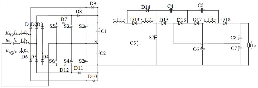
[0056] Specific implementation mode one: the following combination figure 1 This embodiment is described. The topology of a high-power charging device based on a three-level rectifier described in this embodiment includes a pre-stage three-level rectifier and a post-stage DC-DC converter;

[0057] The pre-stage three-level rectifier includes inductor La, inductor Lb, inductor Lc, diode D1, diode D2, diode D3, diode D4, diode D5, diode D6, diode D7, diode D8, diode D9, diode D10, diode D11, diode D12, switching tube S1, switching tube S2, switching tube S3, switching tube S4, switching tube S5, switching tube S6, capacitor C1 and capacitor C2;

[0058] The post-stage DC-DC converter includes inductor L1, inductor L2, inductor L3, switch S7, diode D13, diode D14, diode D15, diode D16, diode D17, diode D18, capacitor C3, capacitor C4, capacitor C5, capacitor C6 , capacitor C7, capacitor C8 and switch tube S7;

[0059] One end of the inductor La is connected to the grid-side pow...

specific Embodiment

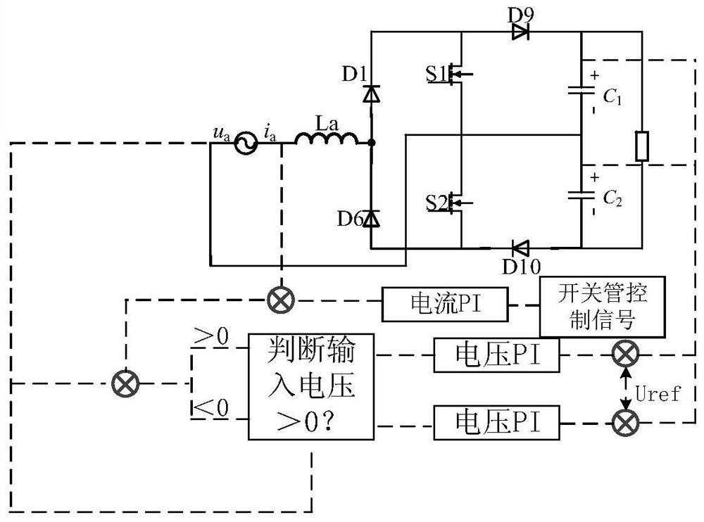
[0098] The control block diagram of the pre-stage AC-DC part is as follows image 3 As shown, the following combination image 3 Explain the specific control process:

[0099] A, collect the voltage of the capacitors C1 and C2 on the output side of the rectifier, and the three-phase voltage and current on the input side;

[0100] B. Comparing the sampled two capacitor voltages with a given reference voltage to obtain two voltage error signals of capacitor C1 and capacitor C2 respectively;

[0101] C, judge the positive or negative of the input voltage;

[0102] D. If the input voltage is positive, the voltage error signal of capacitor C1 is selected as the control signal of the voltage loop, and after the voltage loop PI control, it is output as the input value of the inner loop of the current loop;

[0103] E, if the input voltage is negative, select the voltage error signal of the capacitor C2 as the control signal of the voltage loop, after the voltage loop PI control, t...


PUM


Abstract

The invention relates to a topological structure of a high-power charging device based on a three-level rectifier, which belongs to the technical field of high-power charging. The problem of low reliability, slow response speed and low power level of the existing electric vehicle high-power charging device is solved. The invention includes a front-stage three-level rectifier and a rear-stage DC-DC converter; the front-stage AC-DC part adopts a three-level rectification structure with a neutral line, and its three-phase independent can realize automatic decoupling, and has high power density, Low device voltage stress is convenient for device selection in practical applications, high power factor, simple control method and other advantages. The DC-DC part of the latter stage adopts a secondary boost and an improved voltage doubling unit, which has the advantages of low input current ripple, low device voltage stress, high voltage gain, and wide-range operation. The invention is applicable to the technical field of high-power charging.

Description

technical field [0001] The invention belongs to the technical field of high-power charging. Background technique [0002] With the rapid development of electric vehicles, the development of related supporting infrastructure for electric vehicles must also be accelerated. The most important infrastructure for electric vehicles is the high-power charging device, and the performance of the charging device plays a vital role in the popularization of electric vehicles. Since the charging mode of electric vehicles is developing toward high power and rapidity, high-voltage DC charging devices are required to quickly charge the batteries of electric vehicles. Therefore, designing a high-power charging device with high reliability, strong compatibility, fast response, and high DC output voltage level is of great significance to the further development of the entire automotive industry. [0003] The structure of the existing high-power charging device generally adopts the traditiona...

Claims


Application Information

Patent Timeline
Patent Type & Authority Patents(China)
IPC IPC(8): H02M7/12H02M3/06H02M3/10H02M1/088H02M1/14
CPCH02M7/12H02M3/06H02M3/10H02M1/088H02M1/14
Inventor 杜玖玉刘郑心陈天锦边慧萍
Owner TSINGHUA UNIV
Why Eureka
Try Eureka