
Carbide drill machining and manufacturing method

A cemented carbide, machining and manufacturing technology, which is applied in the field of difficult-to-machine materials in aviation and aerospace, can solve the problems of difficulty in guaranteeing aperture accuracy and surface quality, restricting the scientific research and production of difficult-to-machine materials, and poor cutting performance of materials, so as to save tool costs. and related grinding costs, improve processing efficiency and production bottlenecks, and improve the effect of drilling capacity

Pending Publication Date: 2021-04-13
航天科工哈尔滨风华有限公司
View PDF8 Cites 1 Cited by
  • Summary
  • Abstract
  • Description
  • Claims
  • Application Information

AI Technical Summary

Problems solved by technology

[0002] At present, in the drilling process of products that are difficult to process materials such as high-temperature alloys, low-expansion alloy steels, and ceramic composite matrix materials, the drilling process is very difficult. Due to the hard material and poor cutting performance, ordinary alloy drills often cause burning. It is difficult to guarantee the accuracy of the hole diameter and the surface quality, regardless of the efficiency and cost of the tool or the problem of breaking. The tool can only be changed frequently regardless of efficiency and cost, while grinding and processing, and drilling slowly a little bit, resulting in very low processing efficiency and low processing quality. It is also difficult to guarantee that it is a technical bottleneck that has plagued the processing of such products, an important technical problem that restricts the scientific research and production of difficult-to-process materials, and belongs to a technical blank in China

Method used


Image

  • Carbide drill machining and manufacturing method
  • Carbide drill machining and manufacturing method
  • Carbide drill machining and manufacturing method

Examples


specific Embodiment approach 1

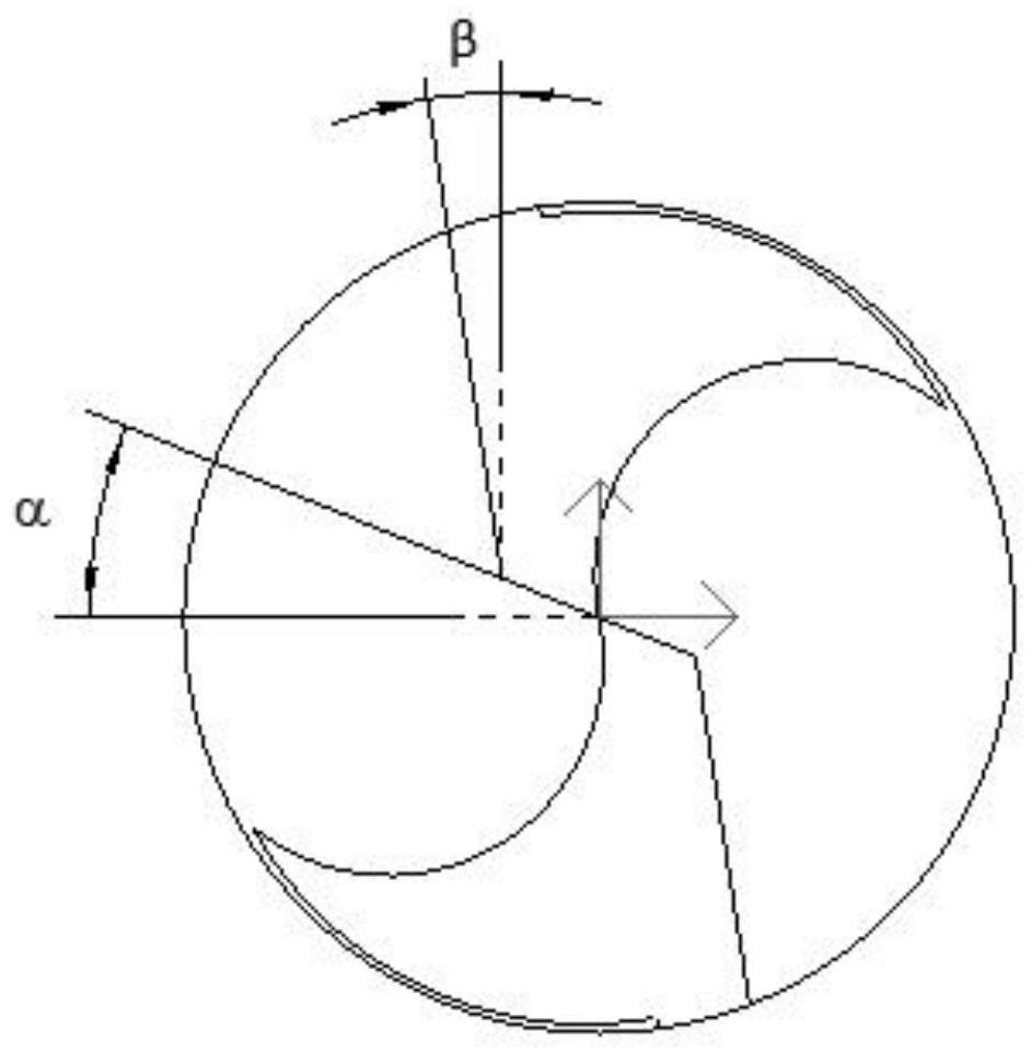
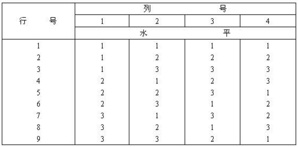
[0037] Specific implementation mode one: combine Figure 1-Figure 2 Describe the present embodiment, the cemented carbide drill processing and manufacturing method of the present embodiment, the cemented carbide drill processing and manufacturing method, it is characterized in that:

[0038] Step 1, use a five-axis high-precision CNC tool grinder to ensure the consistency and precision of the carbide drill;

[0039] Step 2, choose the No. 46 diamond grinding wheel as the grinding tool;

[0040] In step 3, the processing parameters are selected from the cutting experiment parameters, and the optimal parameters of the experiment are: rake angle 11°, horizontal angle α of the first cutting edge, horizontal angle β of the second cutting edge, apex angle γ and lead angle 21°;

[0041] Step 4: Use small feed and multiple grinding methods to process and manufacture cemented carbide drill bits to ensure the accuracy of various angles. In the multiple grinding method, the linear speed...


PUM


Abstract

The invention discloses a carbide drill machining and manufacturing method, and belongs to the field of aviation and aerospace difficult-to-machine materials. The original drill tip form is changed, a composite form drill tip is innovatively researched and developed, and the cutting angle of a cutter is optimized through statistical analysis of cutting test data, so that a special novel drill cutter is formed to be mainly used for drilling machining of products made of high-temperature alloy, low-expansion alloy steel and ceramic composite base materials; and a design and manufacturing method for innovating the shape of the drill tip in a targeted mode and optimizing the angle of the cutter is used for meeting the requirement for drilling machining of products made of difficult-to-machine materials in scientific research and production. The cutting angles of the drill are reasonably compared through experiments, and the optimal machining angle is selected, so that wear resistance is achieved; on the other hand, a stepped cutting edge is added, so that the situation that the drill is damaged and scrapped due to the fact that the temperature of the drill is too high since the drill always uses a first cutting edge for machining is prevented; and optimization is reasonable, practicability and reliability are achieved, difficult-to-machine materials can be effectively drilled, and the blank in the field of the method in China is filled.

Description

technical field [0001] The invention relates to a method for manufacturing a cemented carbide drill bit, which belongs to the field of aviation and aerospace difficult-to-machine materials. Background technique [0002] At present, in the drilling process of products that are difficult to process materials such as high-temperature alloys, low-expansion alloy steels, and ceramic composite matrix materials, the drilling process is very difficult. Due to the hard material and poor cutting performance, common alloy drills often cause burning. It is difficult to guarantee the accuracy of the hole diameter and the surface quality, regardless of the efficiency and cost of the tool or the problem of breaking. The tool can only be changed frequently regardless of efficiency and cost, while grinding and processing, and drilling slowly a little bit, resulting in very low processing efficiency and low processing quality. It is also difficult to guarantee that it is a technical bottlenec...

Claims


Application Information

Patent Timeline
Patent Type & Authority Applications(China)
IPC IPC(8): B24B3/24B24B1/00
CPCB24B3/24B24B1/00
Inventor 张翼飞吕博
Owner 航天科工哈尔滨风华有限公司
Learn More