
Steel coil unreeling machine

A technology of unwinding machine and steel coil, which is applied in the field of steel coil unwinding machine, which can solve the problems such as inconvenient lifting and setting of steel coil, and achieve the effect of reducing burden and improving work efficiency

Pending Publication Date: 2021-04-13
重庆讯通精密模具有限公司
View PDF13 Cites 3 Cited by
  • Summary
  • Abstract
  • Description
  • Claims
  • Application Information

AI Technical Summary

Problems solved by technology

[0004] Aiming at the deficiencies in the prior art, the present invention provides a steel coil unwinding machine, which solves the problem in the prior art that it is inconvenient to lift the steel coil and set it on the rotating shaft

Method used


Image

  • Steel coil unreeling machine
  • Steel coil unreeling machine
  • Steel coil unreeling machine

Examples


Embodiment Construction

[0014] The technical solutions in the present invention will be further described below in conjunction with the accompanying drawings and embodiments.

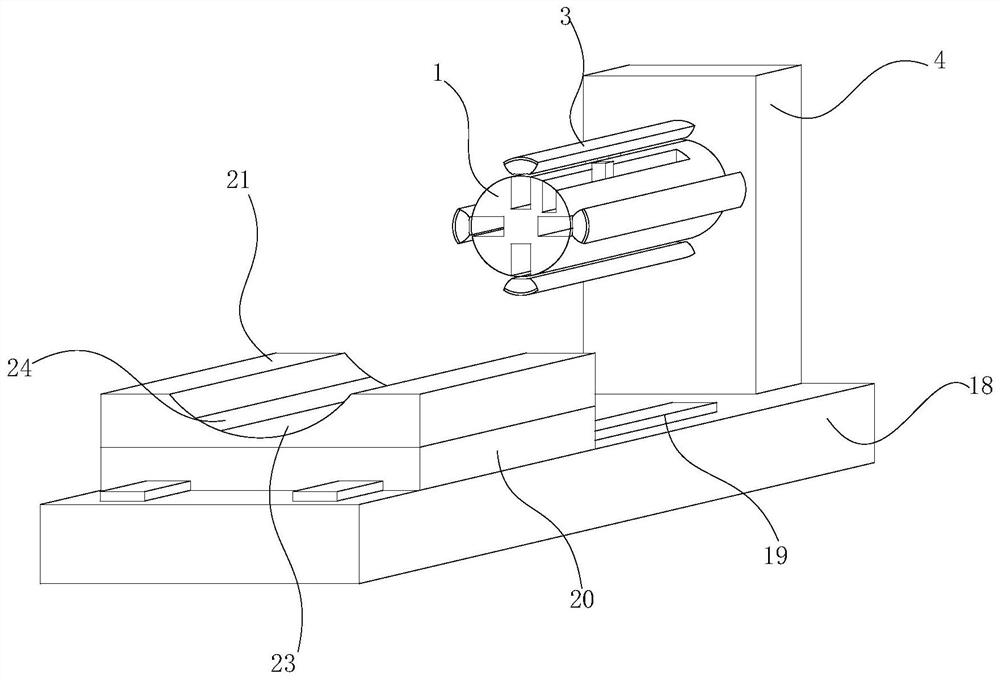
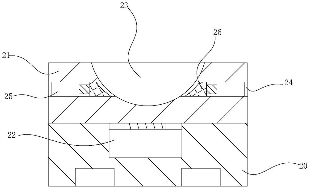
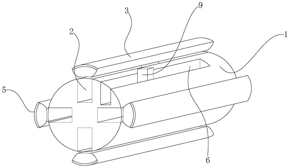
[0015] Such as figure 1 as well as figure 2 As shown, the embodiment of the present invention proposes a steel coil unwinding machine, including: a base 18, a sliding seat 20 and a base 21, the top of the base 18 is provided with a guide rail 19, and the sliding seat 20 is slidably arranged on On the guide rail 19, the bottom of the base 18 is provided with a cylinder for driving the sliding seat 20 to slide on the guide rail 19, the base 21 is placed on the top of the sliding seat 20, and the top of the sliding seat 20 is recessed to form a second installation groove, the second installation groove is provided with a fourth hydraulic cylinder 22 for pushing the base 21 to move in the vertical direction, and the top of the base 21 is provided with a support groove 23 for placing a steel strip coil. Both side walls of the su...


PUM


Abstract

The invention provides a steel coil unreeling machine. The steel coil unreeling machine comprises a base, a sliding seat and a base; a guide rail is arranged at the top of the base, the sliding seat is arranged on the guide rail in a sliding mode, an air cylinder used for driving the sliding seat to slide on the guide rail is arranged at the bottom of the base, and the base is placed at the top of the sliding seat; the top of the sliding seat is sunken to form a second mounting groove, a fourth hydraulic cylinder used for pushing the base to move in the vertical direction is arranged in the second mounting groove, a supporting groove used for containing a steel strip coil is formed in the top of the base, and at least one third sliding groove is formed in each of the two side walls of the supporting groove; a clamping assembly used for preventing the steel strip coil from swinging in the supporting groove is arranged in each third sliding groove; a mounting plate is further vertically arranged at the top of the base, a roller is rotatably arranged on the side, close to the base, of the mounting plate, and the roller is used for penetrating through an inner ring of the steel strip coil; and a motor for driving the roller to rotate is arranged on the mounting plate.

Description

technical field [0001] The invention relates to the technical field of steel strip processing equipment, in particular to a steel coil unwinding machine. Background technique [0002] Steel belt refers to the conveyor belt made of carbon steel as the traction and carrying member of the belt conveyor, and can also be used to bundle goods. [0003] During the handling and storage of the steel strip, in order to save the storage space of the steel strip, the steel strip is usually coiled into a coil for storage, but when the steel strip needs to be used or the steel strip needs to be reprocessed, the coil needs to be rolled into a coil Unwind the steel strip to facilitate the processing of the steel strip. When unwinding the steel strip, the steel strip must be lifted first, so that the steel strip is set on the rotating shaft, and then driven by the motor The rotating shaft drives the steel strip coil to rotate, so that the steel strip coil releases the steel strip. Because t...

Claims


Application Information

Patent Timeline
Patent Type & Authority Applications(China)
IPC IPC(8): B21C47/18B21C47/24B21C47/30B21C47/32B21C47/34
CPCB21C47/18B21C47/24B21C47/30B21C47/32B21C47/34
Inventor 陈忠平
Owner 重庆讯通精密模具有限公司
Learn More