
Thin film unreeling device

A technology of unwinding device and film, applied in the direction of winding strip, thin material processing, transportation and packaging, etc., can solve problems such as film material wear and tear

Inactive Publication Date: 2018-05-22
CHANGDE JINDE NEW MATERIAL TECH CO LTD
View PDF10 Cites 1 Cited by
  • Summary
  • Abstract
  • Description
  • Claims
  • Application Information

AI Technical Summary

Problems solved by technology

[0004] Based on this, it is necessary to provide a film unwinding device that can effectively prevent the wear of the f

Method used


Image

  • Thin film unreeling device
  • Thin film unreeling device
  • Thin film unreeling device

Examples


Embodiment Construction

[0020] In order to facilitate the understanding of the present invention, the present invention will be described more fully below with reference to the associated drawings. Preferred embodiments of the invention are shown in the accompanying drawings. However, the present invention can be embodied in many different forms and is not limited to the embodiments described herein. On the contrary, these embodiments are provided to make the understanding of the disclosure of the present invention more thorough and comprehensive.

[0021] It should be noted that when an element is referred to as being “fixed” to another element, it can be directly on the other element or there can also be an intervening element. When an element is referred to as being "connected to" another element, it can be directly connected to the other element or intervening elements may also be present. The terms "vertical," "horizontal," "left," "right," and similar expressions are used herein for purposes ...


PUM


Abstract

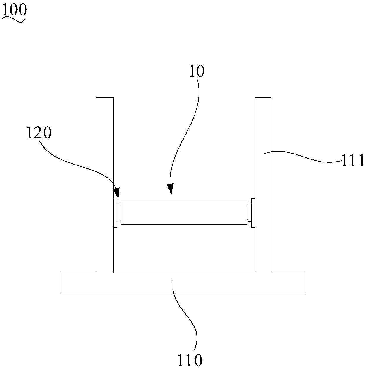
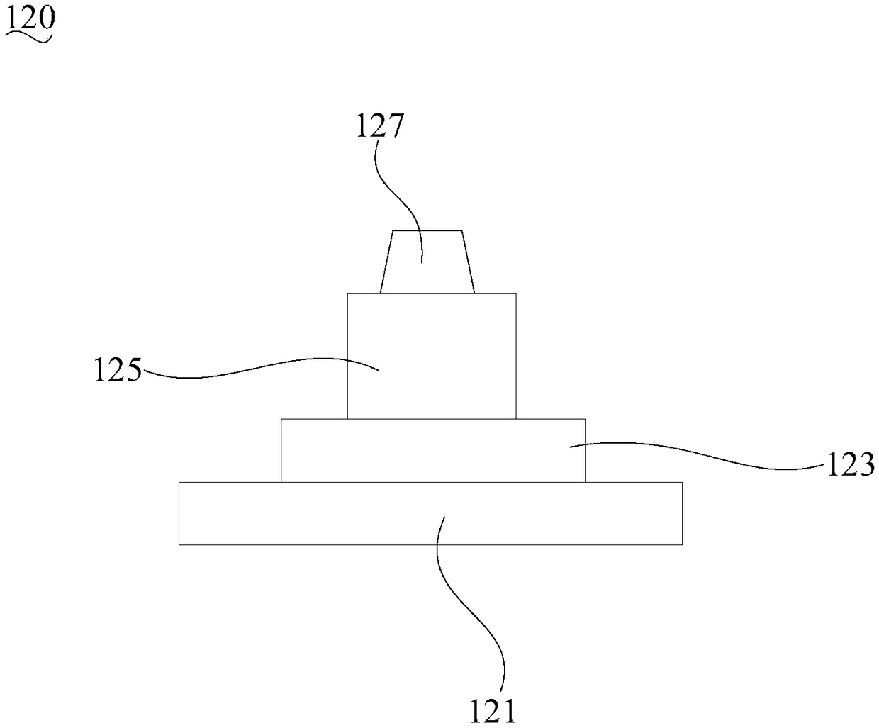
The invention relates to a thin film unreeling device. The thin film unreeling device comprises a rack and two reels which are arranged on the rack in a spaced mode, wherein each reel comprises a base, a limiting stand disposed on the surface of the base and a supporting column which is disposed on the surface of the limiting stand. Before unreeling, the two ends of a reeling core are arranged onthe supporting columns of the two opposite reels correspondingly in a sleeving mode; furthermore, the reeling core is driven with the supporting columns as shafts, and then unreeling of thin film materials can be achieved; and moreover the tail end of the reeling core can abut against the limiting stands. The size, in the second direction, of each limiting stand can be designed to be larger than the inner diameter of the reeling core but slightly smaller than the outer diameter of the reeling core. Therefore, the limiting stands can prevent the thin film materials from sliding towards the bases, and meanwhile the limiting stands cannot make contact with the thin film materials reeled on the reeling core, that is, the tail ends of the thin film materials on the reeling core are not rubbed during unreeling so that the thin film materials can be effectively prevented from being abraded.

Description

technical field [0001] The invention relates to the technical field of film material processing, in particular to a film unwinding device. Background technique [0002] Thin film materials are used more and more widely. For example, laser film commonly used in the packaging field, solar film in solar power generation technology. For the convenience of storage and transportation, the film material is generally a large roll structure after forming, and the film material is wound on the core. Therefore, before using the film material, unwinding is required to unfold the film material. [0003] At present, the unwinding equipment generally includes a frame and an unwinding shaft arranged on the frame. The winding core is sleeved on the unwinding shaft, and unwinding is realized by rotating on the unwinding shaft. However, the unwinding shaft in the existing unwinding equipment is generally a columnar structure. During unwinding, the edges of the roll of film material may co...

Claims


Application Information

Patent Timeline
IPC IPC(8): B65H16/06
Inventor 余赞冯杰蒋何峰彭程陈爱国杜建军
Owner CHANGDE JINDE NEW MATERIAL TECH CO LTD
Learn More