
Tail wire protection mechanism for computer and operation method of tail wire protection mechanism

A protection mechanism, computer technology, applied in the direction of bendable lead devices, etc., can solve the problems of tail wire damage, lack of tail wire, and tail wire dragging to the ground.

Inactive Publication Date: 2021-11-05
嘉兴市荣刚科技有限公司
View PDF0 Cites 0 Cited by
  • Summary
  • Abstract
  • Description
  • Claims
  • Application Information

AI Technical Summary

Problems solved by technology

[0002] During the computer connection process, it is necessary to use tail wires to connect multiple electrical devices at different locations. However, due to the different positions of the devices, the length of the tail wires is fixed, resulting in the tail wire being in a tight state or the length of the tail wire of the device far away. Insufficient, and the closer equipment will cause the tail wire to drag the ground, making the tail wire vulnerable to damage
[0003] The existing technology lacks an adjustment device for the length of the tail wire, which leads to low adaptability of the tail wire during the connection process and is easily affected by environmental factors, resulting in unstable connection with the computer
[0004] To this end, a computer tail wire protection mechanism and its operation method are provided to solve the problem of adapting and adjusting the tail wire connection length

Method used


Image

  • Tail wire protection mechanism for computer and operation method of tail wire protection mechanism
  • Tail wire protection mechanism for computer and operation method of tail wire protection mechanism
  • Tail wire protection mechanism for computer and operation method of tail wire protection mechanism

Examples


Embodiment Construction

[0030] The following will clearly and completely describe the technical solutions in the embodiments of the present invention with reference to the accompanying drawings in the embodiments of the present invention. Obviously, the described embodiments are only some, not all, embodiments of the present invention. Based on the embodiments of the present invention, all other embodiments obtained by persons of ordinary skill in the art without making creative efforts belong to the protection scope of the present invention.

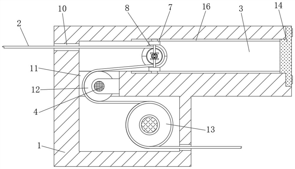
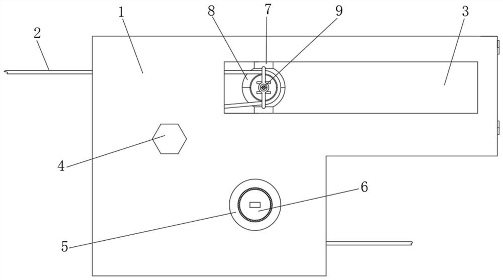
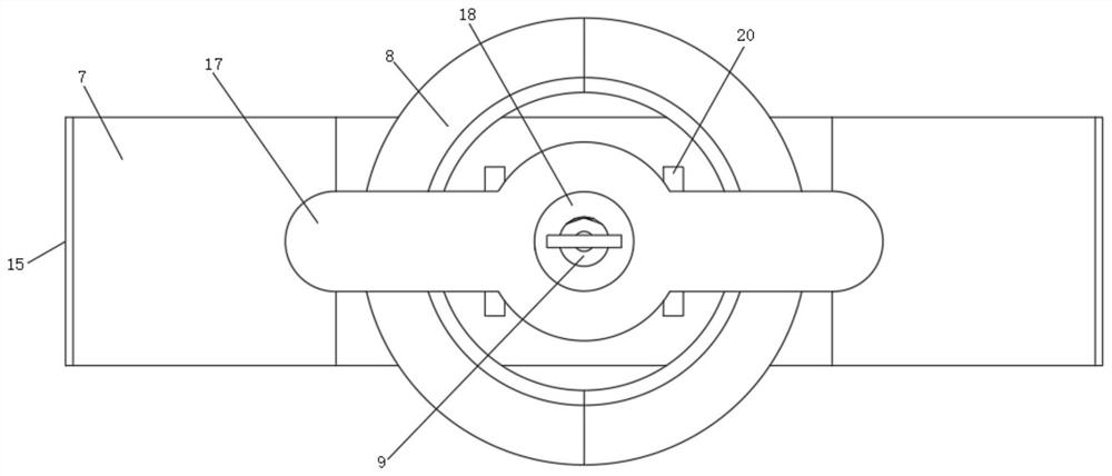
[0031] see Figure 1 to Figure 6 , the present invention provides a technical solution:

[0032] A tail wire protection mechanism for a computer, comprising a protective block 1, a sliding base 7 is slidably installed in the rear inner cavity of the protective block 1, a screw-fixed end cover 14 is arranged on the right side of the adjusting inner cavity 3, and the adjusting inner cavity 3 A pair of symmetrical chute 16 is provided on the rear side of the fro...


PUM


Abstract

The invention relates to the technical field of computer cable connection, in particular to a tail wire protection mechanism for a computer and an operation method of the tail line protection mechanism. The tail wire protection mechanism comprises a protection block, a sliding base is slidably installed in an inner cavity of the rear side of the protection block, and a winding roller with a winding spiral groove is vertically sleeved with an inner cavity of the front end of the protection block, and a rotatably-mounted guide wheel is arranged between front the inner cavity and the rear inner cavity of the protection block. The mechanism has the beneficial effects that the base capable of being adjusted in a sliding mode is arranged, smooth extension of the tail line is achieved, meanwhile, fine adjustment of the extension length of the tail line is achieved through adjustment of the position of the sliding base, and meanwhile, a conical rod at the lower end of a second threaded rod is used for extruding a semicircular clamping ring, so the length of the tail wire position is fixed; by arranging the winding roller with the spiral groove, storage of the length of the tail line is achieved, and rotation of the first threaded rod is matched, so that coarse adjustment of the length of the tail line is achieved, the length of the tail line is matched with equipment connection at different positions, and the situation that transmission of a computer is affected by tail line connection is avoided.

Description

technical field [0001] The invention relates to the technical field of computer cable connection, in particular to a tail wire protection mechanism for a computer and an operation method thereof. Background technique [0002] During the computer connection process, it is necessary to use tail wires to connect multiple electrical devices at different locations. However, due to the different positions of the devices, the length of the tail wires is fixed, resulting in the tail wire being in a tight state or the length of the tail wire of the device far away. Insufficient, and the closer equipment will cause the tail wire to drag the ground, which makes the tail wire vulnerable to damage. [0003] The prior art lacks a device for adjusting the length of the tail wire, which leads to low adaptability of the tail wire during the connection process and is easily affected by environmental factors, thereby causing instability in connection with the computer. [0004] Therefore, a c...

Claims


Application Information

Patent Timeline
Patent Type & Authority Applications(China)
IPC IPC(8): H01R13/72
CPCH01R13/72
Inventor 陈涛
Owner 嘉兴市荣刚科技有限公司
Learn More