
Distributed regulator structure for achieving optimized regulator properties and increased valve service life

A technology for adjusting mechanisms and structures, applied in brakes, vehicle parts, transportation and packaging, etc., can solve problems such as target conflicts, and achieve the effect of simplifying assembly

Pending Publication Date: 2021-04-09
KNORR BREMSE SYST FUR SCHIENENFAHRZEUGE GMBH
View PDF9 Cites 0 Cited by
  • Summary
  • Abstract
  • Description
  • Claims
  • Application Information

AI Technical Summary

Problems solved by technology

This leads to conflicting objectives if both functions are integrated into one valve at the same time

Method used


Image

  • Distributed regulator structure for achieving optimized regulator properties and increased valve service life
  • Distributed regulator structure for achieving optimized regulator properties and increased valve service life
  • Distributed regulator structure for achieving optimized regulator properties and increased valve service life

Examples


Embodiment Construction

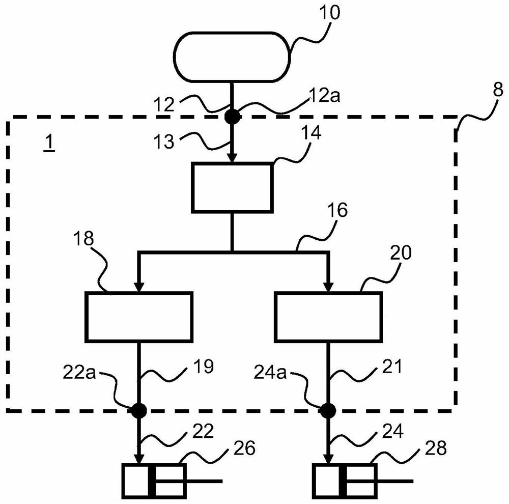
[0066] figure 1 A schematic diagram of the principle of the device 1 according to the invention is shown. Shown is a pressure accumulator 10 , in particular a compressed air accumulator, which is connected via a supply line 12 , which is connected to an inlet opening 12 a of the housing 8 of the device 1 . The device 1 is supplied with a pressure medium, subsequently referred to as compressed air, via the pressure accumulator 10 . However, other embodiments using other media are also conceivable.

[0067] In this case, the pressure accumulator 10 does not have to be connected directly to the device 1 as shown. Alternatively, the pressure accumulator can also be connected to a plurality of devices 1 , the connection thus taking place, for example, via branching supply lines 12 .

[0068] Inside the device 1 there is provided a relay valve 14 which receives compressed air via a connecting line 13 which is connected to the inlet opening 12a. Relay valve 14 is designed to esta...


PUM


Abstract

A device (1) for regulating a pneumatic brake pressure of a vehicle is disclosed, having: an inlet opening (12a) which is designed to be connected to a pressure accumulator (10), at least one outlet opening (22a, 24a) which is designed to be connected to a brake device (26, 28) in order to activate same, and at least two actuator elements (14, 18, 20) which are arranged between the inlet opening (12a) and the at least one outlet opening (22a, 24a) and which are designed to influence a brake pressure between the inlet opening (12a) and the at least one outlet opening (22a, 24a). In addition, a control device (40), a system (5), a brake system, a method and a computer program product are disclosed.

Description

technical field [0001] The invention relates to a device, a control device, a system and a brake system for influencing the brake pressure of a vehicle, in particular a rail vehicle. The invention also relates to a method and a computer program product for influencing the brake pressure of a vehicle. Background technique [0002] To influence the brake pressure of the vehicle, in particular the pneumatic brake pressure, (pre-control) valves are used. In pressure regulation, there is often a conflict of objectives between the required number of switching gaps and the achievable accuracy or the achievable height and slope of the individual pressure steps. The latter directly affects the quality of pressure regulation. In a vehicle, shocks can be felt here due to the gradual change in pressure and thus delay. This affects driving comfort. In addition, negative influences, in particular wear influences, on the components used of the corresponding brake system are determined ...

Claims


Application Information

Patent Timeline
Patent Type & Authority Applications(China)
IPC IPC(8): B60T13/66B60T13/68B60T8/50
CPCB60T13/66B60T13/68B60T8/5012
Inventor M·菲舍尔M·霍尔茨M-O·赫登J-J·沃赫
Owner KNORR BREMSE SYST FUR SCHIENENFAHRZEUGE GMBH
Learn More