Eureka AIR delivers breakthrough ideas for toughest innovation challenges, trusted by R&D personnel around the world.

Electromagnetic repulsion rapid mechanism and rapid mechanical switch

An electromagnetic repulsion and fast technology, applied in electric switches, high-voltage/high-current switches, circuits, etc., can solve problems such as the impact of the arc extinguishing chamber, the impact of the operating mechanism body, shortening the service life of the operating mechanism and the arc extinguishing chamber, etc. To achieve the effect of prolonging the service life, avoiding impact and shortening the opening and closing time

Active Publication Date: 2021-04-09
PINGGAO GRP +2
View PDF12 Cites 0 Cited by
  • Summary
  • Abstract
  • Description
  • Claims
  • Application Information

AI Technical Summary

Problems solved by technology

[0005] The multiple acceleration coils provided by the above-mentioned electromagnetic repulsion operating mechanism provide moving channels for the movement of the repulsion disk on the one hand, and accelerate the opening and closing movement of the repulsion disk on the other hand, but in practical applications, if the closing of the repulsion disk If the speed is too high, it will cause a great impact on the arc extinguishing chamber. Similarly, if the opening speed is too high, it will cause a great impact on the body of the operating mechanism, which will shorten the service life of the operating mechanism and the arc extinguishing chamber
In addition, multiple acceleration coils are used to form a moving channel, which requires high precision for the movement of the repulsion disk. The repulsion disk must not be in contact with the acceleration coil, otherwise the acceleration coil will be damaged and cause serious failure.

Method used


Image

  • Electromagnetic repulsion rapid mechanism and rapid mechanical switch
  • Electromagnetic repulsion rapid mechanism and rapid mechanical switch
  • Electromagnetic repulsion rapid mechanism and rapid mechanical switch

Examples


Embodiment Construction

[0059] In order to make the object, technical solution and advantages of the present invention clearer, the present invention will be further described in detail below in conjunction with the accompanying drawings and embodiments. It should be understood that the specific embodiments described here are only used to explain the present invention, and are not intended to limit the present invention, that is, the described embodiments are only some of the embodiments of the present invention, but not all of the embodiments. The components of the embodiments of the invention generally described and illustrated in the figures herein may be arranged and designed in a variety of different configurations.

[0060] Accordingly, the following detailed description of the embodiments of the invention provided in the accompanying drawings is not intended to limit the scope of the claimed invention, but merely represents selected embodiments of the invention. Based on the embodiments of the...


PUM


Abstract

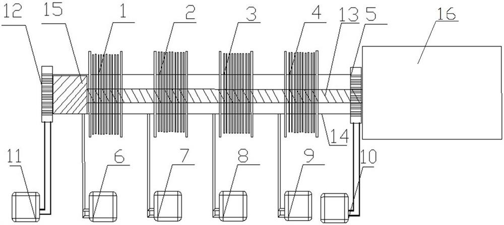
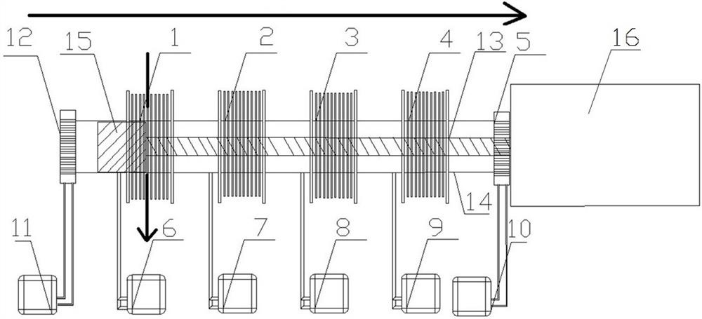
The invention provides an electromagnetic repulsion rapid mechanism and a rapid mechanical switch. The electromagnetic repulsion rapid mechanism comprises: a transmission rod; an induction disc fixed on the transmission rod; an opening repulsion coil; a closing repulsion coil; at least two electromagnetic coils; and electromagnetic coil control circuits which are connected with the electromagnetic coils in a one-to-one correspondence mode so as to control power-on and power-off of the electromagnetic coils. In the opening and closing process, at least one of the electromagnetic coils is an acceleration coil, the acceleration coil is powered on at the front half section and powered off at the rear half section where the induction disc passes, at least one of the electromagnetic coils is a deceleration coil, and the deceleration coil is powered off at the front half section and powered on at the rear half section where the induction disc passes. The induction disc is accelerated by the acceleration coil in the early stage of opening and closing, the overall opening and closing time is shortened, meanwhile, the induction disc is decelerated by the deceleration coil in the later stage of opening and closing, impact on the arc extinguishing chamber or the operating mechanism body due to overhigh speed is avoided, and the service life of the operating mechanism and the arc extinguishing chamber is prolonged.

Description

technical field [0001] The invention relates to the technical field of high-voltage switchgear, in particular to an electromagnetic repulsion fast mechanism and a fast mechanical switch. Background technique [0002] The current fast mechanical switch mainly includes a repulsion mechanism and a moving end assembly. The repulsion mechanism includes a charger, an energy storage capacitor, a thyristor, a repulsion coil, and a repulsion disk. The moving end assembly includes a moving contact, a moving contact seat, and a driving moving contact. The transmission rod moves in the opening and closing direction. After the switch is powered on, the charger charges the energy storage capacitor and buffer capacitor for opening and closing. When the switch is closed, the system receives the closing command and triggers the thyristor that controls the discharge. At this time, the thyristor is turned on, and the current passes through the thyristor. The closing coil is discharged. At thi...

Claims


Application Information

Patent Timeline
Patent Type & Authority Applications(China)
IPC IPC(8): H01H33/38H01H33/42
CPCH01H33/38H01H33/42
Inventor 姚文彬孙英杰熊萍萍孙珂珂董佩冉李久良门博张良杰井琼琼张利欣胡延涛
Owner PINGGAO GRP
Why Eureka
Eureka Blog
Learn More