Efficient injection-suction type hydraulic impactor

A hydraulic impactor and ejector-suction technology, which is applied to the driving device for drilling in the borehole, drilling equipment, earthwork drilling and production, etc., can solve the problems of high start-up and working pressure, unstable performance, and low energy utilization rate

Pending Publication Date: 2021-04-09
BEIJING RES INST OF URANIUM GEOLOGY
View PDF0 Cites 2 Cited by
  • Summary
  • Abstract
  • Description
  • Claims
  • Application Information

AI Technical Summary

Problems solved by technology

[0006] The purpose of the present invention is to provide a high-efficiency jet-suction hydraulic impactor for the defects of large start-up flow rate, high start-up and working pressure, unstable performance, and low energy utilization rate of the jet-suction hydraulic impactor in the prior art. By installing a fixed jet-suction unit composed of a nozzle and a spray-bearing element in the impactor, the parameters of the jet-suction structure are fixed, resulting in stable jet-suction performance, which can effectively improve the reliability of the hydraulic impactor and improve the utilization of water energy. rate, reduce the starting flow and working pressure, and improve the working performance of the hydraulic impactor

Method used


Image

  • Efficient injection-suction type hydraulic impactor
  • Efficient injection-suction type hydraulic impactor
  • Efficient injection-suction type hydraulic impactor

Examples


Embodiment Construction

[0033] The present invention will be described in further detail below in conjunction with the accompanying drawings and embodiments.

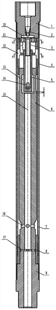
[0034] As shown in Figure 1, a high-efficiency jet-suction hydraulic impactor provided by the present invention includes an upper joint 1, a nozzle 2, a nozzle holder 3, a limit guide sleeve 4, a live valve 5, and an impact hammer rod 6. Outer pipe 7, lower cylinder liner 8, impact anvil joint 9. The lower end surface of the upper joint 1 is provided with an inner counterbore 10 with a depth of 1 mm to 20 mm, and a cavity space is formed between the inner counterbore 10 and the injector 3 . The upper part of the upper joint 1 is threadedly connected with the drill pipe, and the nozzle 2 is pressed into the center hole of the upper joint 1 through interference fit. The position is fixed, the taper of the inner taper hole at the upper part of the nozzle 2 is 0°~150°, and the diameter of the inner hole at the lower end is 1.5mm~50mm.

[0035] T...


PUM

PropertyMeasurementUnit
Diameteraaaaaaaaaa
Depthaaaaaaaaaa
Depthaaaaaaaaaa

Abstract

The invention belongs to the field of drilling machinery, and particularly relates to an efficient injection-suction type hydraulic impactor. The efficient injection-suction type hydraulic impactor comprises an upper connector, a nozzle, a spray bearing device, a limiting guide sleeve, a movable valve, an impact hammer rod, an outer pipe, a lower cylinder sleeve and an impact anvil block connector, wherein the nozzle is installed in a center hole of the upper connector, the lower portion of the upper connector is installed in the upper end of the outer pipe, the limiting guide sleeve is installed in an inner hole in the upper portion of the outer pipe, an upper limiting step of the movable valve is hung at the position of a limiting ring of the limiting guide sleeve, the upper end of the spray bearing device is installed in an inner hole in the upper end of the limiting guide sleeve, a guide pipe at the lower end of the spray bearing device is inserted into an inner hole in the upper end of the movable valve, and the upper end of the impact hammer rod is installed in an inner hole in the lower portion of the limiting guide sleeve; and the lower end of the impact hammer rod and the upper end of the impact anvil block connector are both installed in the lower cylinder sleeve, the upper portion of the impact anvil block connector is installed in the lower end of the outer pipe, and the lower cylinder sleeve is installed in an inner hole in the lower portion of the outer pipe. According to the efficient injection-suction type hydraulic impactor, the stable injection-suction performance can be generated, the starting flow and the working pressure are reduced, and the working performance of the hydraulic impactor is improved.

Description

technical field [0001] The invention belongs to the field of drilling machinery, and in particular relates to a high-efficiency jet-suction hydraulic impactor. Background technique [0002] The hydraulic impactor is installed on the rotary drilling tool as an auxiliary rock breaking tool and is widely used in drilling and drilling fields, including geological and mineral resource drilling, oil drilling, shale gas drilling, coalbed methane drilling, hydrological water well drilling, engineering construction, etc. field. It is beneficial to improve the drilling efficiency, improve the core recovery rate, prevent the broken rock formation from jamming the drilling tool, improve the service life of the drill bit, and control the deviation of the drilling hole. [0003] The live valve and impact hammer of the injection-suction hydraulic impactor mainly rely on the entrainment force generated by the nozzle to make them go upward. When they are in the upper position, the hammer va...

Claims


Application Information

Patent Timeline
IPC IPC(8): E21B4/16E21B12/00E21B10/61
CPCE21B4/16E21B12/00E21B10/61
Inventor 刘晓阳李博
Owner BEIJING RES INST OF URANIUM GEOLOGY
Why Eureka
Try Eureka