Chucking apparatus for a workpiece with honeycomb structure

a technology of workpieces and chucking apparatuses, which is applied in mechanical apparatus, manufacturing tools, transportation and packaging, etc., can solve the problems of unsuitability for some applications, limited bending of clamping plates, and high work intensity of clamping plates, so as to achieve the effect of little effor

Active Publication Date: 2018-05-01
GFM GMBH
View PDF12 Cites 1 Cited by
  • Summary
  • Abstract
  • Description
  • Claims
  • Application Information

AI Technical Summary

Benefits of technology

[0006]The invention is thus based on the object of providing a chucking apparatus for a workpiece with honeycomb structure to be machined on both honeycomb sides such that chucking conditions which correspond to direct chucking of the workpiece on a table with suction can be ensured with relatively little effort for the workpiece that has already been machined on one honeycomb side.
[0008]The open-cell structure of the clamping plate allows constant suction engagement through the clamping plate over the entire receiving surface, because the open-cell structure of the clamping plate allows constant suction of the entire receiving surface into which the open structural cells lead. This means that a workpiece with honeycomb structure, which is placed with its already profiled surface surface covered by an air-tight film onto the receiving surface of the clamping plate with the same shape, is held by the open-cell structure of the clamping plate in a manner which can certainly be compared with direct suction of the as yet unprocessed workpiece on the table. The constant chucking of the workpiece over the entire receiving surface of the clamping plate promotes the machining of the workpiece especially in thin boundary regions which have lower own strength, because the workpiece is effectively sucked towards the receiving surface also in the area of these thin wall regions.
[0009]Especially advantageous constructional conditions are obtained when the open-cell structure of the clamping plate is achieved by a honeycomb structure, because in this case the honeycombs, which determine the receiving surface with their face ends, form flow channels which are aligned in parallel in the suction direction, are separated from each other by the honeycomb walls, and not only have comparatively large flow cross-sections, but also offer a respectively low flow resistance.
[0010]The centering of the workpiece in relation to the clamping plate requires respective measures due to the honeycomb structure of the clamping plate. Advantageous centering of the workpiece in relation to the receiving surface of the clamping plate can advantageously be achieved in such a way that the clamping plate, adjacent to the receiving surface for the workpiece, forms a re-entrant centering stop which cooperates with a counter stop of the workpiece. The counter stop of the workpiece thus protrudes against the already profiled surface, so that said counter stops support the holding down of the workpiece in the region of the boundary regions to be machined, since said counter stops only need to be separated after the machining of the second surface of the workpiece.

Problems solved by technology

It is an additional factor that the machining of the clamping plates, which are usually made of a light metal, is work-intensive.
However, such bending is only possible within limits and unsuitable for some applications.

Method used


Image

  • Chucking apparatus for a workpiece with honeycomb structure
  • Chucking apparatus for a workpiece with honeycomb structure
  • Chucking apparatus for a workpiece with honeycomb structure

Examples


Embodiment Construction

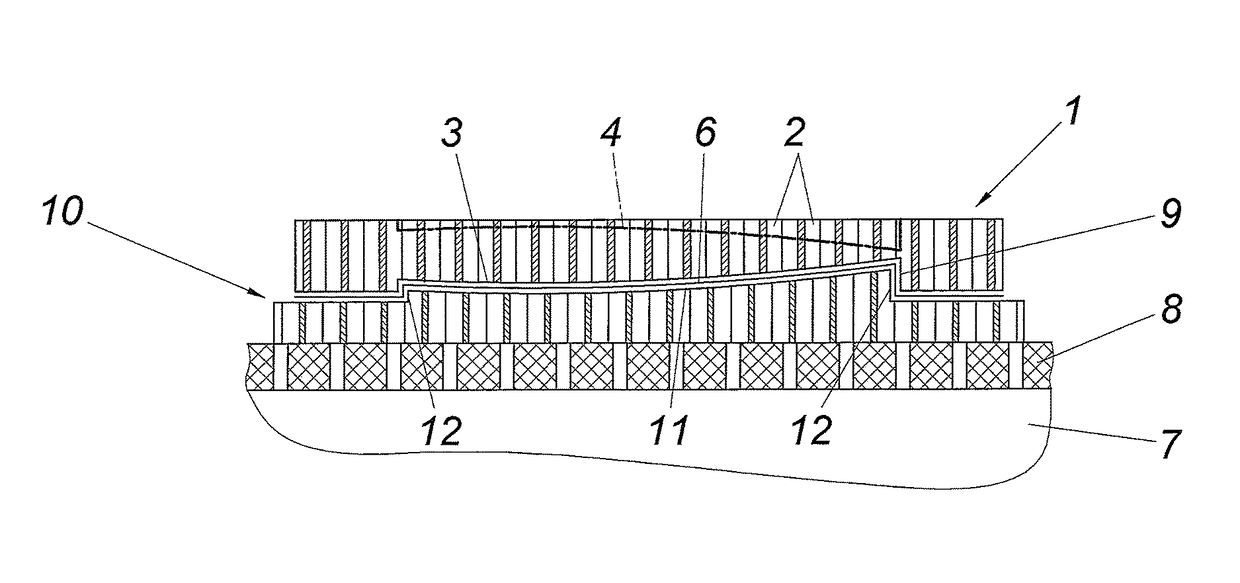
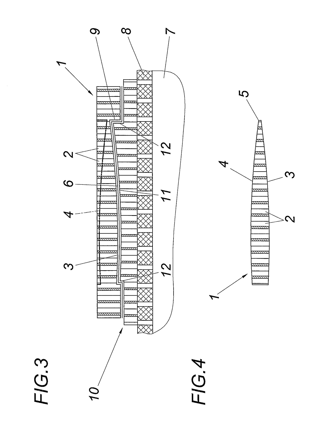
[0017]The machined workpiece 1 with a honeycomb structure, e.g. the core of a wing profile, comprises two mutually opposite profiled surfaces 3 and 4 according to FIG. 4, which are respectively determined by the face ends of the honeycombs 2 and which taper off on a longitudinal side of the workpiece 1 into a thin edge 5.

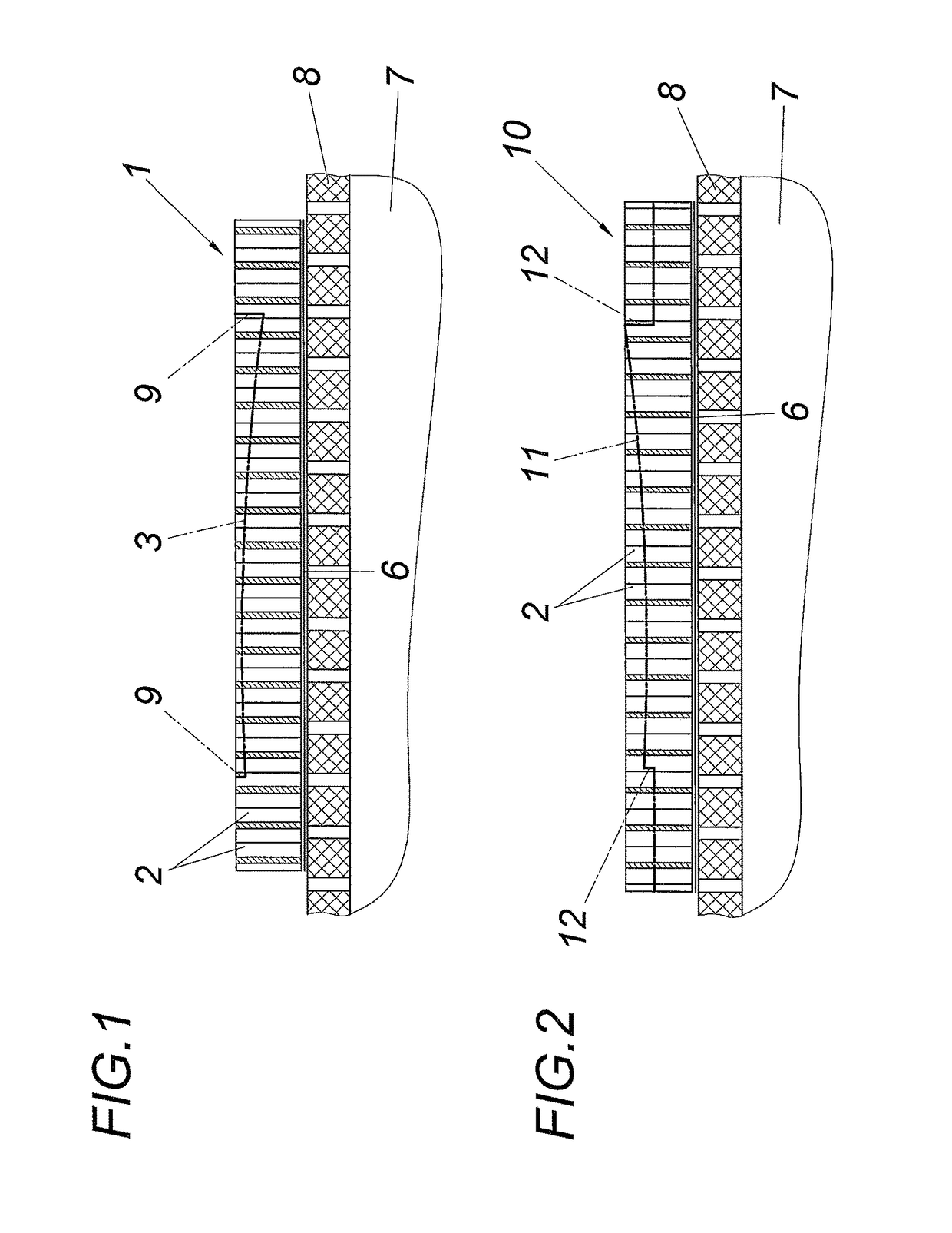
[0018]A honeycomb plate with parallel surfaces is assumed for the production of such a workpiece 1 according to FIG. 1, which surfaces are masked on one side by an air-tight film 6 in order to be placed in an aligned manner with said masked side on an air-permeable table 8 which is connected to a suction box 7. As a result of the application of a vacuum to the table 8 via the suction box 7, the workpiece 1 is clamped down on the table 8 ready for machining. The one of the two surfaces 3, 4 can thus be machined with a multi-axis machining apparatus which is fitted with cutter or milling tools. The surface 3 to be machined is shown in a dot-dash line in FIG. 1. The bo...


PUM


Abstract

A chucking apparatus for a workpiece with honeycomb structure includes a table that can be supplied with vacuum and a clamping plate which can be placed on the table and which accommodates the workpiece in the region of an already profiled surface determined by the face ends of the honeycombs, whose receiving surface, which corresponds to the profiled surface of the workpiece, is provided with suction openings to the table. In order to provide advantageous chucking conditions, the clamping plate has an open-cell structure.

Description

CROSS REFERENCE TO RELATED APPLICATIONS[0001]Applicant claims priority under 35 U.S.C. § 119 of Austrian Application No. A50310 / 2014 filed Apr. 29, 2014, the disclosure of which is incorporated by reference.BACKGROUND OF THE INVENTION[0002]1. Field of the Invention[0003]The invention relates to a chucking apparatus for a workpiece with honeycomb structure, comprising a table that can be supplied with a vacuum and a clamping plate which can be placed on the table and which accommodates the workpiece in the region of an already profiled surface which is determined by the face ends of the honeycombs, whose receiving surface corresponding to the negative shape of the profiled surface of the workpiece is provided with suction openings to the table.[0004]2. Description of the Related Art[0005]Lightweight components, as are used in the construction of aircraft for example, comprise a core with honeycomb structure which is joined with cover layers into a composite body. Since the core repre...

Claims


Application Information

Patent Timeline
Patent Type & Authority Patents(United States)
IPC IPC(8): B23B31/30B23Q3/06B26D3/00B25B11/00B23Q3/08B26D7/01B64F5/10
CPCB23B31/307B23Q3/062B23Q3/088B25B11/005B26D7/018B26D3/006Y10T279/11B23B2215/04B23Q2703/04B64F5/10B23Q3/065B23Q3/10B23Q2703/10
Inventor HEIDLMAYER, FRANZ
Owner GFM GMBH
Why Eureka
Try Eureka