A flipping electromagnet system for a baler

A technology of electromagnet and baler, which is applied to conveyors, non-mechanical conveyors, transportation and packaging, etc. It can solve the problems of delay in discharging, long time, and uncontrollable placement methods, etc., and achieves rapid suction and discharge. smooth release effect

Active Publication Date: 2016-01-20
LONGI MAGNET CO LTD
View PDF7 Cites 0 Cited by
  • Summary
  • Abstract
  • Description
  • Claims
  • Application Information

AI Technical Summary

Problems solved by technology

However, the traditional lifting device, that is, the magnetic lifting equipment, cannot guarantee the alternate placement of the docking; and the traditional magnetic lifting equipment takes a long time due to the factors of excitation and energy release during the process of absorbing and discharging materials, which seriously affects the production efficiency. Occupies a lot of site space and consumes manpower and financial resources
In addition, on-site operators are required to perform electromagnet control and steel auxiliary placement, which poses a huge potential safety hazard
[0003] At present, traditional electromagnetic lifting equipment has been plagued by the following two problems in practical application. These two problems have always been the problems faced in the process of placing and lifting steel before bundling: 1. Lifting of steel and release of dependence Lifting electromagnets occupy too much space on site, and the transportation process is not stable, the placement method is uncontrollable, and coherence and centralized control cannot be achieved. It requires a lot of labor, with half the effort, resulting in waste of resources, and the equipment is not easy to maintain, and there are potential safety hazards; 2. The flip-type electromagnet used in part 2, even if the placement method is guaranteed to be controllable, due to the instability of the magnetic field during the rotation process, the steel will fall off, and the magnetic energy consumption is slow during placement, and the discharge time is delayed, resulting in low production efficiency. Device contacts are easily damaged

Method used


Image

  • A flipping electromagnet system for a baler
  • A flipping electromagnet system for a baler
  • A flipping electromagnet system for a baler

Examples


Embodiment Construction

[0016] The following will clearly and completely describe the technical solutions in the embodiments of the present invention with reference to the accompanying drawings in the embodiments of the present invention. Obviously, the described embodiments are only part of the embodiments of the present invention, not all of them. Based on the embodiments of the present invention, all other embodiments obtained by persons of ordinary skill in the art without making creative efforts belong to the protection scope of the present invention. Additionally, the protection scope of the present invention should not be limited only to the following specific structures or components or specific parameters.

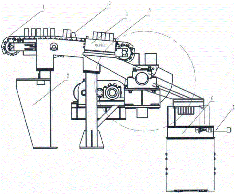
[0017] The overturning electromagnet system for a baler of the present invention mainly includes a transmission chain 1, a support frame 2, a chain stopper 3, an electromagnet 4, a suction cup stopper 5, a bundling platform 6, a hydraulic device 7, a supporting plate 8, and Turn axis 9. ...


PUM


Abstract

The invention provides an overturning electromagnet system for a bundling machine, which comprises a conveying chain (1), a supporting frame (2), chain check blocks (3), electromagnets (4), sucker check blocks (5), a bundling platform (6) and a hydraulic device (7), wherein the electromagnets (4), the sucker check blocks (5), bearing supporting plates (8) and rotating shafts (9) are in key connection and fixed by bolts. The overturning electromagnet system for the bundling machine is applicable to the iron and steel manufacturing industry, is especially used for bundling and packing H-shaped steel, angle steel, flat steel and steel channels, solves the problem of absorption and stably reversed release of steel during the bundling process in a steel mill, realizes the centralized control function, and has the advantages of space conservation, firmness in absorption, quickness and stability in discharging, centralized control, easiness in operation, convenience in maintenance, safety, reliability and the like.

Description

technical field [0001] The invention belongs to the field of magnetic transfer machinery, and in particular relates to an overturning electromagnet system for a baler, which is suitable for the steel transfer system in the steel manufacturing industry with a large processing capacity, especially for the packaging process of H-shaped steel, angle steel, and channel steel Turning solenoid system designed for balers. Background technique [0002] As more and more magnetic transfer devices are used in the transportation field, magnetic transfer devices have been widely used in recent years. In the iron and steel manufacturing industry, conventional lifting electromagnets have been used for lifting and placing the entire process of transportation, lifting, bundling, and packaging of steel such as H-shaped steel, angle steel, flat steel, and channel steel. However, the traditional lifting device, that is, the magnetic lifting equipment, cannot guarantee the alternate placement of...

Claims


Application Information

Patent Timeline
Patent Type & Authority Patents(China)
IPC IPC(8): B65G54/02
Inventor 张承臣徐家林史玉林张小琳纪常付
Owner LONGI MAGNET CO LTD
Why Eureka
Try Eureka