Novel aluminum alloy auxiliary frame

A technology of aluminum alloy and sub-frame, which is applied to vehicle parts, substructure, transportation and packaging, etc., can solve the problems of difficult quality control, many parts brackets, and many processes, saving development costs and tooling costs, guaranteeing Consistency, the effect of improving mechanical properties

Inactive Publication Date: 2021-04-09
HOZON NEW ENERGY AUTOMOBILE CO LTD
View PDF8 Cites 3 Cited by
  • Summary
  • Abstract
  • Description
  • Claims
  • Application Information

AI Technical Summary

Problems solved by technology

At present, the subframe is mainly made of steel stamped and welded subframe, and the connection structure of the steel stamped and welded subframe is generally in the form of stamped and welded brackets, which are connected to the main body of the subframe by welding, but there are subframes with this structure. Focus on the shortcomings of heavy weight, many parts and brackets, many and long welds, many processes, and difficult to control quality

Method used


Image

  • Novel aluminum alloy auxiliary frame
  • Novel aluminum alloy auxiliary frame
  • Novel aluminum alloy auxiliary frame

Examples


Embodiment 1

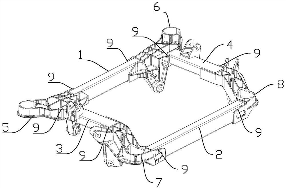
[0026] A new type of aluminum alloy sub-frame, including a front beam 1, a rear beam 2, a left side beam 3 and a right side beam 4, the front beam 1, rear beam 2, left side beam 3 and right side beam 4 are all made of aluminum Alloy profiles are extruded to form a hollow tubular structure;

[0027] The subframe also includes a left front mounting bracket 5, a right front mounting bracket 6, a left rear mounting bracket 7 and a right rear mounting bracket 8; the left front mounting bracket 5, the right front mounting bracket 6, the left rear mounting bracket 7 and the right rear mounting bracket The brackets 8 are all cast from aluminum alloy; the two ends of the left front mounting bracket 5, the right front mounting bracket 6, the left rear mounting bracket 7 and the right rear mounting bracket 8 are provided with assembly grooves 9;

[0028] The two ends of the front beam 1 are respectively installed in the assembly grooves 9 of the left front mounting bracket 5 and the righ...

Embodiment 2

[0030] A new type of aluminum alloy sub-frame, including a front beam 1, a rear beam 2, a left side beam 3 and a right side beam 4, the front beam 1, rear beam 2, left side beam 3 and right side beam 4 are all made of aluminum Alloy profiles are extruded to form a hollow tubular structure;

[0031] The subframe also includes a left front mounting bracket 5, a right front mounting bracket 6, a left rear mounting bracket 7 and a right rear mounting bracket 8; the left front mounting bracket 5, the right front mounting bracket 6, the left rear mounting bracket 7 and the right rear mounting bracket The brackets 8 are all cast from aluminum alloy; the two ends of the left front mounting bracket 5, the right front mounting bracket 6, the left rear mounting bracket 7 and the right rear mounting bracket 8 are provided with assembly grooves 9;

[0032] The two ends of the front beam 1 are respectively installed in the assembly grooves 9 of the left front mounting bracket 5 and the righ...


PUM


Abstract

The invention discloses a novel aluminum alloy auxiliary frame which comprises a front cross beam, a rear cross beam, a left longitudinal beam and a right longitudinal beam, and the front cross beam, the rear cross beam, the left longitudinal beam and the right longitudinal beam are all of a hollow tubular structure formed by extrusion forming of aluminum alloy sections. The auxiliary frame further comprises a left front mounting bracket, a right front mounting bracket, a left rear mounting bracket and a right rear mounting bracket; the left front mounting bracket, the right front mounting bracket, the left rear mounting bracket and the right rear mounting bracket are all formed by casting aluminum alloy. According to the novel aluminum alloy auxiliary frame, through the front cross beam, the rear cross beam, the left longitudinal beam and the right longitudinal beam which are formed through extrusion, the weight is light, the yield is high, the cost is low, and welding is easy to control; the left front mounting bracket, the right front mounting bracket, the left rear mounting bracket and the right rear mounting bracket need to be connected with other parts of a vehicle body or a chassis, structural changes are complex, and the mechanical performance of casting parts formed through casting is improved.

Description

technical field [0001] The invention relates to the field of automobile manufacturing, in particular to a novel aluminum alloy auxiliary frame. Background technique [0002] At present, the global automobile production and ownership are increasing, and the safety requirements for automobiles are also getting higher and higher. The sub-frame is an important part of the current mainstream car chassis. The structural form, stiffness and strength of the sub-frame have a great impact on the durability, comfort and handling of the vehicle. It is an important basis for measuring the design level of the car chassis. Therefore, the research on the structure design and optimization technology of the sub-frame of the automobile has attracted much attention. At present, the subframe is mainly made of steel stamped and welded subframe, and the connection structure of the steel stamped and welded subframe is generally in the form of stamped and welded brackets, which are connected to the...

Claims


Application Information

Patent Timeline
Patent Type & Authority Applications(China)
IPC IPC(8): B62D21/02
CPCB62D21/02
Inventor 白甫停江翁王飞余进超
Owner HOZON NEW ENERGY AUTOMOBILE CO LTD
Why Eureka
Try Eureka