
A magnetic liquid polishing device for optical lens processing

A magnetic liquid and polishing device technology, applied in the direction of grinding/polishing safety devices, optical surface grinders, metal processing equipment, etc., can solve the problems of time-consuming, complicated adjustment, cumbersome structure, etc., to improve the efficiency of disassembly and assembly, adjustment The effect of simple method and simple position adjustment

Active Publication Date: 2021-05-28
朗信(苏州)精密光学有限公司
View PDF0 Cites 0 Cited by
  • Summary
  • Abstract
  • Description
  • Claims
  • Application Information

AI Technical Summary

Problems solved by technology

[0006] The existing magnetic liquid polishing device has the following defects due to its cumbersome structure, troublesome disassembly and assembly, and low efficiency of assembly and adjustment:
[0007] (1) When replacing the polishing wheel, the entire polishing device needs to be disassembled. The disassembly and assembly workload is huge, and the performance of key parts is easily affected during disassembly, and it is often difficult to achieve the performance before disassembly after reassembly; Disassemble and reassemble the position of the magnetic field generating device inside the polishing wheel, which further increases the workload of reassembly;
[0008] (2) The position adjustment of the recovery device is complicated. When installing and adjusting the recovery device, due to its inherent structure, it is difficult to adjust the position of the recovery device relative to the polishing wheel, and the adjustment efficiency is low;
[0009] (3) The adjustment of the liquid spray pipe device is cumbersome. The position of the liquid spray pipe device of the existing polishing device is either not adjustable, or the adjustment is complicated, especially after each polishing wheel is replaced, it needs to be readjusted, which takes a long time

Method used


Image

  • A magnetic liquid polishing device for optical lens processing
  • A magnetic liquid polishing device for optical lens processing
  • A magnetic liquid polishing device for optical lens processing

Examples


Embodiment Construction

[0031] The present invention will be further described below in conjunction with the accompanying drawings and specific embodiments.

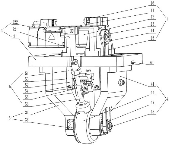
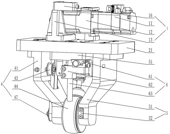
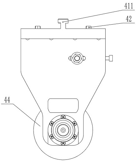
[0032] Such as Figure 1 to Figure 8 As shown, a magnetic liquid polishing device for optical lens processing includes a motor assembly 1, a motor 11, a reducer 12, a motor mounting seat 13, a main timing pulley 14, a timing belt 15, and a liquid inlet pipe clamping seat 16. Installation and fixing device 2, installation and fixing plate 21, chute 211, T-shaped slider avoidance hole 212, pipe clamp seat 221, pipe clamp 222, left arm module 3, left installation arm 31, magnetic field generator 32, installation Block 33, cover plate 34, right arm module 4, right mounting arm 41, slider 411, tapered pin 42, tensioning wheel 43, tensioning wheel shaft 431, polishing wheel 44, rolling bearing 45, sleeve 46, driven synchronization Pulley 47, retaining ring 48, recovery device 5, mounting seat 51, support shaft 52, recovery pipe seat 53, up and down ...


PUM


Abstract

The invention discloses a magnetic liquid polishing device for optical lens processing. The motor assembly is fixed on the upper end surface of the installation and fixing device. A left arm module and a right arm module are oppositely arranged on the lower end surface of the installation and fixing device. The lower end of the left installation arm passes through the The installation block is fixedly connected with the magnetic field generator, the outer periphery of the installation block is installed with a cover plate, the upper end of the right installation arm is installed with a slider, the slider is connected with the chute, the two sides of the slider are provided with tapered pins, and the middle of the right installation arm is installed A tension pulley is arranged, and a recovery device is installed on the fixing device, and the recovery device is connected with the liquid spray pipe device. The invention has a simple structure, adopts the modular design of the left arm module, the right arm module, and the recovery device, and each module is independently installed on the installation and fixing device. When replacing the polishing wheel, it is not necessary to dismantle the entire polishing device, only the right arm needs to be disassembled Modules are enough, which greatly improves the efficiency of disassembly and assembly, and at the same time avoids damage to key components caused by large-scale disassembly and assembly.

Description

technical field [0001] The invention relates to the technical field of ultra-precision processing equipment for optical elements, in particular to a magnetic liquid polishing device for processing optical lenses. Background technique [0002] Magnetic liquid polishing technology is an important ultra-precision processing method in the field of optical component processing. Compared with traditional optical polishing technology, magnetic liquid polishing technology does not produce sub- Surface damage, and high processing efficiency. Magnetic liquid is a smart material composed of magnetic particles, carrier liquid, polishing powder and other additives. The magnetic particles in the magnetic liquid can produce obvious magnetorheological effects under the action of a magnetic field. According to the size of the external magnetic field, it can be Fast and reversible switching between liquid and solid or semi-solid. When the magnetic liquid is delivered from the nozzle to the u...

Claims


Application Information

Patent Timeline
Patent Type & Authority Patents(China)
IPC IPC(8): B24B1/00B24B13/00B24B55/00
CPCB24B1/005B24B13/00B24B55/00
Inventor 刘念明李文坚
Owner 朗信(苏州)精密光学有限公司
Learn More