Steel structure profile welding method

A welding method and steel structure technology, applied in welding equipment, welding equipment, auxiliary welding equipment, etc., can solve problems that affect welding efficiency and contact end welding difficulties, so as to improve welding efficiency, facilitate turning work, and facilitate welding operations Effect

Inactive Publication Date: 2021-04-09
深圳市中阳源石油化工有限公司
View PDF0 Cites 0 Cited by
  • Summary
  • Abstract
  • Description
  • Claims
  • Application Information

AI Technical Summary

Problems solved by technology

It gets its name because its cross-section is the same as the English letter "T". When steel is used in some areas, it is necessary to butt weld H-shaped steel and T-shaped steel. When in use, it is convenient to weld the upper end of the butt joint of H-shaped steel and T-shaped steel, but it is difficult to weld the other contact ends of the butt joint, which will affect the welding efficiency. Therefore, it is necessary to design a welding method for steel structure profiles to solve the above problems.

Method used


Image

  • Steel structure profile welding method
  • Steel structure profile welding method
  • Steel structure profile welding method

Examples


Embodiment Construction

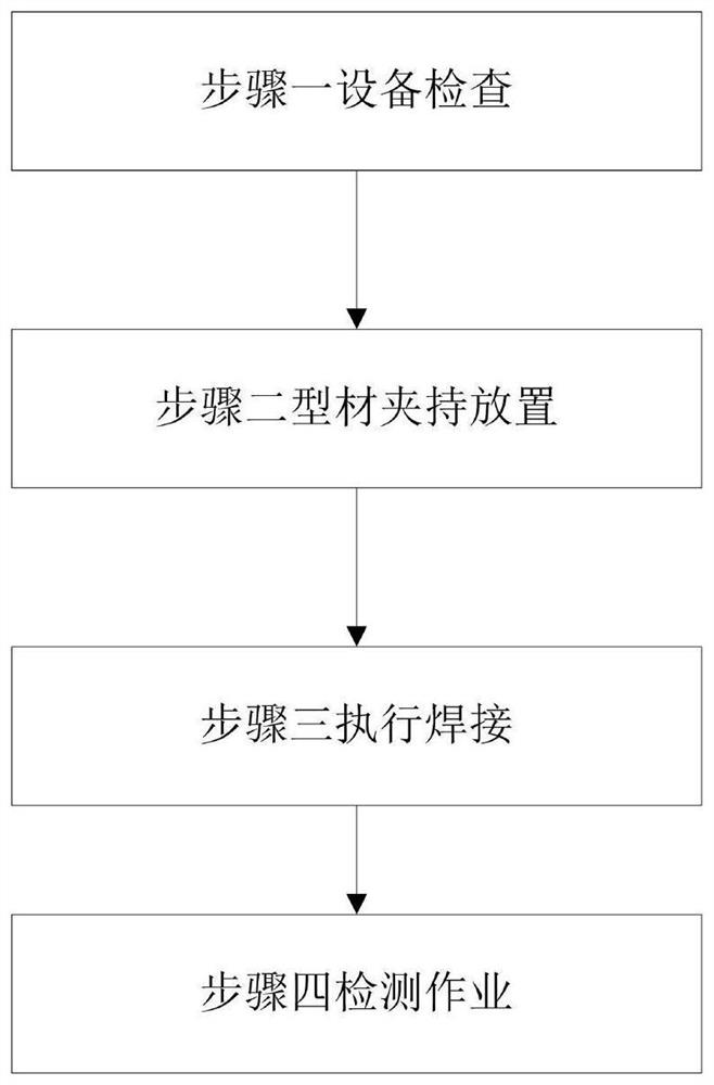
[0028] In order to make the technical means, creative features, goals and effects achieved by the present invention easy to understand, the present invention will be further described below in conjunction with specific embodiments.

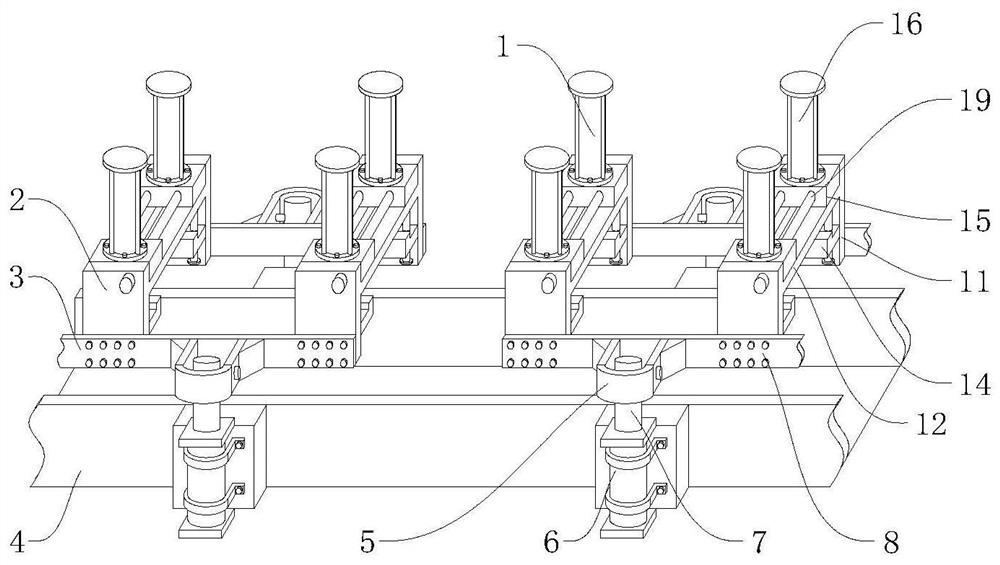
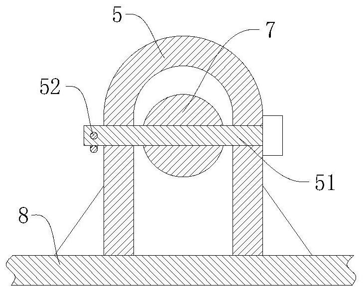
[0029] see Figure 1-Figure 5 , the present invention provides a technical solution: a welding method for steel structure profiles, which uses a counter-position fixing device, which includes a first clamping mechanism 1, a second clamping mechanism 2, a first fixing plate 3, U-shaped collection box 4, U-shaped fixed frame 5, first lifting cylinder 6, push rod 7 and second fixed plate 8, two second fixed plates 8 arranged horizontally and transversely are symmetrically installed on the upper right side of U-shaped collection box 4, and pass The U-shaped collection box 4 provides an installation carrier for the first lifting cylinder 6, and also effectively collects the welding slag generated by welding. The two second fixing plates 8 are equidista...


PUM


Abstract

The invention relates to the technical field of steel structures, in particular to a steel structure profile welding method. The steel structure profile welding method uses an alignment fixing device, and the device comprises first clamping mechanisms, second clamping mechanisms, first fixing plates, a U-shaped collecting box, U-shaped fixing frames, first lifting cylinders, push rods and second fixing plates. H-shaped steel is fastened and clamped through the first clamping mechanisms, then the opposite ends of T-shaped steel and the H-shaped steel are in butt joint, the T-shaped steel is fastened and clamped through the second clamping mechanisms, and through the first lifting cylinders at one end of the U-shaped collecting box, under the action of the push rods, the U-shaped fixing frames, the first fixing plates and the second fixing plates, the first clamping mechanisms and the second clamping mechanisms are synchronously overturned, so that the T-shaped steel and the H-shaped steel are synchronously overturned, the side end of one side of the butt joint position is outwards overturned to form a proper angle, and the side end of the other side of the butt joint position can be outwards overturned to form a proper angle through the first lifting cylinders at the other end of the U-shaped collecting box.

Description

technical field [0001] The invention relates to a steel structure profile welding method, which belongs to the technical field of steel structures. Background technique [0002] H-shaped steel is an economical cross-section high-efficiency profile with more optimized cross-sectional area distribution and more reasonable strength-to-weight ratio. It is named because its section is the same as the English letter "H". Section steel is a kind of steel cast into a T shape. It gets its name because its cross-section is the same as the English letter "T". When steel is used in some areas, it is necessary to butt weld H-shaped steel and T-shaped steel. When in use, it is convenient to weld the upper end of the butt joint of H-shaped steel and T-shaped steel, but it is difficult to weld the other contact ends of the butt joint, which will affect the welding efficiency. Therefore, it is necessary to design a welding method for steel structure profiles to solve the above problems. C...

Claims


Application Information

Patent Timeline
Patent Type & Authority Applications(China)
IPC IPC(8): B23K31/02B23K37/04
CPCB23K31/022B23K37/0443
Inventor 梁坤谢光辉周莉
Owner 深圳市中阳源石油化工有限公司
Why Eureka
Try Eureka