


Quick Research
Generate reliable direction feasibility study reports for your R&D in just a few steps.

Technical Q&A
Discover and master advanced knowledge NOW. Basics, ideas, possibilities, all at once.

Find Solutions
As an expert in R&D theories, this can generate solutions to your technical problems instantly.

Evaluate Feasibility
Analyze your overall solution with one click, know your potential R&D risks in advance.

Monitor Landscape
Get weekly tech updates, stay abreast of the latest tech innovations and key insights.
System for removing acid gas in waste incineration
An acid gas and waste incineration technology, applied in gas treatment, dispersed particle filtration, membrane technology, etc., can solve problems such as the failure to reach the reaction temperature of dry deacidification, the inability to cool the flue gas of the boiler, and the easy excess of flue gas emissions. , to achieve the effect of ensuring long-term economic operation, saving resources and reducing the number of shutdowns
- Summary
- Abstract
- Description
- Claims
- Application Information
AI Technical Summary
Problems solved by technology
Method used
Image

Examples
Embodiment 1
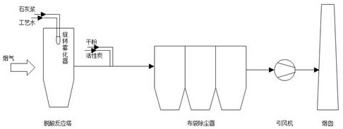
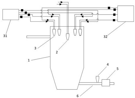
[0042] The overall deacidification process of the present invention is different from that of the prior art figure 1 The same, but the deacidification reaction tower and the setting in the pipeline are different. to combine Figure 2-3A system for removing acid gas in waste incineration, comprising a control host, a deacidification reaction tower 1, a bag filter, an induced draft fan and a chimney.
[0043] The deacidification reaction tower 1 is provided with a gas inlet and a gas outlet. The gas outlet of the deacidification reaction tower 1 is connected to the bag filter through the first pipeline 6. The bag filter is connected to the induced draft fan through the second pipeline, and the induced draft fan introduces the gas into the chimney to be discharged. ;
[0044] The deacidification reaction tower 1 is equipped with a rotary atomizer 2 inside, and the melody atomizer sprays out a mixture of process water and lime slurry to remove the acid gas in the flue gas; the p...
Embodiment 2
[0052] The method of using the above-mentioned device is as follows:
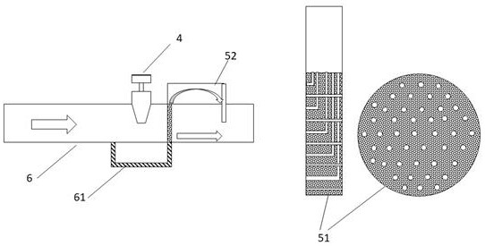
[0053] The temperature value detected by the temperature detector 4 is T, the acid gas concentration detected by the acid gas concentration detector 5 is D, the unit time supply of lime slurry and process water is M, and the unit time supply of slaked lime of the special nozzle for slaked lime is N, The opening number of the two-fluid atomizing spray gun 3 is P;
[0054] Among them, because the work of lime slurry and process water and the work of the two-fluid atomization spray gun 3 will affect the temperature T of the flue gas, so the control host detects whether the temperature T is greater than the optimum temperature T0 of dry acid removal, if T > T0, then increase the number P of the two-fluid atomizing spray gun 3 to be opened; if T<T0, then reduce the number P of the two-fluid atomizing spray gun 3 to be opened;
[0055] In addition, because the work of lime slurry and process water and the work o...
PUM
| Property | Measurement | Unit |
|---|---|---|
| clearance rate | aaaaa | aaaaa |
Abstract
Description
Claims
Application Information
 - R&D Engineer
- R&D Manager
- IP Professional
- Industry Leading Data Capabilities
- Powerful AI technology
- Patent DNA Extraction
Browse by: Latest US Patents, China's latest patents, Technical Efficacy Thesaurus, Application Domain, Technology Topic, Popular Technical Reports.
© 2024 PatSnap. All rights reserved.Legal|Privacy policy|Modern Slavery Act Transparency Statement|Sitemap|About US| Contact US: help@patsnap.com