Structured light coding method based on wrapped phase forward and reverse
A technology that wraps phase and encoding methods, applied in the field of optical three-dimensional shape measurement, can solve problems such as limiting measurement applications, achieve the effects of reducing the number of images, improving efficiency, and greatly practical potential
- Summary
- Abstract
- Description
- Claims
- Application Information
AI Technical Summary
Problems solved by technology
Method used
Image
Examples
Embodiment 1
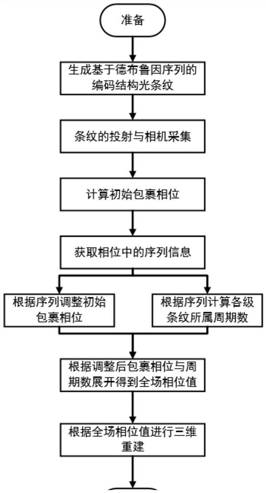
[0034] This embodiment discloses a structured light encoding method based on the positive and negative wrapping phases. Taking the three-step phase shift method, 16 fringe periods, and De Bruyne sequence as an example, it includes the following steps:
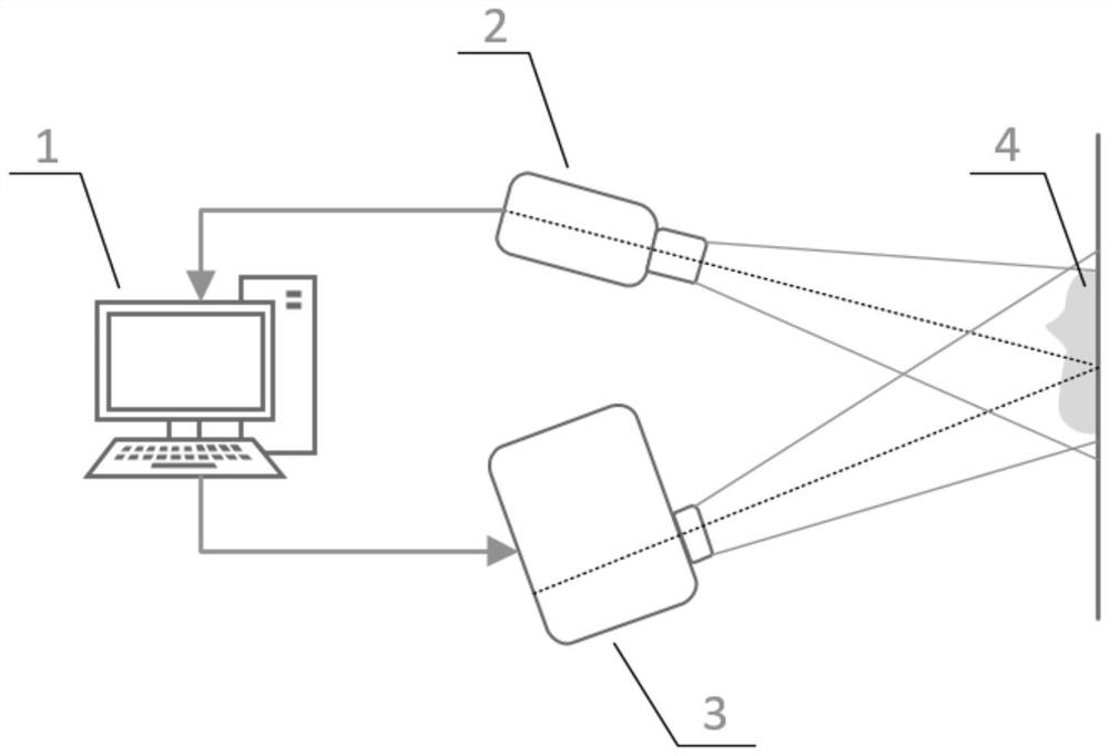
[0035] 1) see figure 1 and figure 2 , to build a structured light measurement system. The structured light measurement system includes a computer 1 , a camera 2 , a projector 3 and a measured object 4 . The camera 2 and the projector 3 are communicably connected to the computer 1 . The camera 2 and the projector 3 are respectively arranged on the front side of the measured object 4, and the arrangement of the structured light measurement system should ensure that the common field of view of the projector 3 and the camera 1 is sufficiently large, and the measured object's measured Features should be covered by the raster projected by this projector 3 . In this embodiment, the optical axes of the projector 3 and the camera 2...
Embodiment 2
[0052] This embodiment provides a relatively basic implementation method, a structured light encoding method based on the positive and negative wrapped phases, taking the three-step phase shift method, 16 fringe periods, and De Bruyne sequence as examples, including the following steps:
[0053] 1) see figure 1 and figure 2 , to build a structured light measurement system. The structured light measurement system includes a computer 1 , a camera 2 , a projector 3 and a measured object 4 . The camera 2 and the projector 3 are communicably connected to the computer 1 . The camera 2 and the projector 3 are respectively arranged on the front side of the measured object 4, and the arrangement of the structured light measurement system should ensure that the common field of view of the projector 3 and the camera 1 is sufficiently large, and the measured object's measured Features should be covered by the raster projected by this projector 3 . In this embodiment, the optical axes...
Embodiment 3
[0066] The main steps of this embodiment are the same as those in Embodiment 2. Further, in step 4), during the process of the computer 1 synthesizing three phase-shifted projection images that contain positive and negative sequence information, the computer 1 compares 0 codes with 1 code, design the corresponding 0 stripe and 1 stripe for each phase shift stripe in the three-step phase shift, and the specific stripe form of each level is as follows:
[0067]
[0068] In formula (2), where n=1,2,3, corresponding to each step of the phase shift image in the three-step phase shift, A is the DC component, B is the amplitude, W 0 is the pixel width (unit) occupied by each level of stripes, and Wherein, W is the width that projector 3 projects a single image, and T is the fringe cycle number, (x 0 ,y 0 ) is the pixel coordinates in the single-level stripe, is the phase shift step size, and the phase shift step size is
[0069] Design the projected grating image according...
PUM
 Abstract
Description
Claims
Application Information
 - Generate Ideas
- Intellectual Property
- Life Sciences
- Materials
- Tech Scout
- Unparalleled Data Quality
- Higher Quality Content
- 60% Fewer Hallucinations
Browse by: Latest US Patents, China's latest patents, Technical Efficacy Thesaurus, Application Domain, Technology Topic, Popular Technical Reports.
© 2025 PatSnap. All rights reserved.Legal|Privacy policy|Modern Slavery Act Transparency Statement|Sitemap|About US| Contact US: help@patsnap.com


