
Automatic fixing piling device

A technology of piling device and fixing device, which is applied in the direction of sheet pile wall, building, foundation structure engineering, etc., and can solve problems such as single function and inability to fix wooden piles

Inactive Publication Date: 2021-04-06
张树文
View PDF0 Cites 1 Cited by
  • Summary
  • Abstract
  • Description
  • Claims
  • Application Information

AI Technical Summary

Problems solved by technology

[0002] The piling device is a common construction machine, but the general piling device cannot fix wooden piles of different thicknesses, and the function is relatively single

Method used


Image

  • Automatic fixing piling device
  • Automatic fixing piling device
  • Automatic fixing piling device

Examples


specific Embodiment approach 1

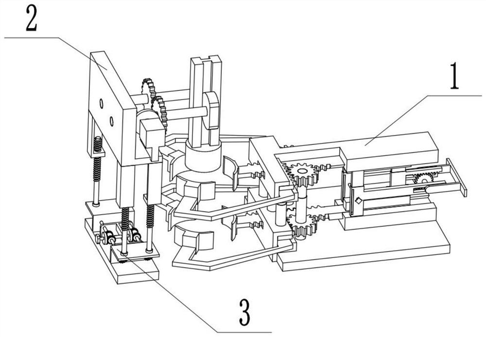
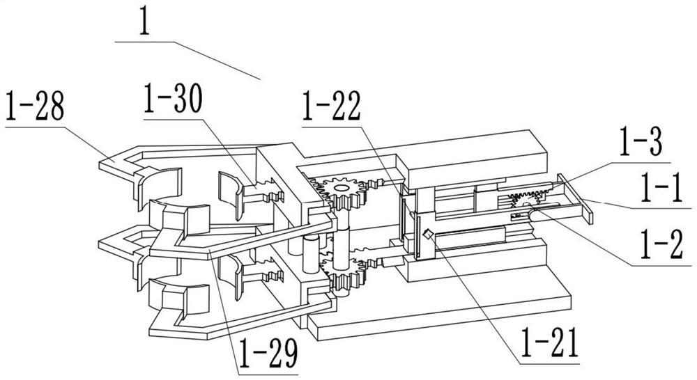
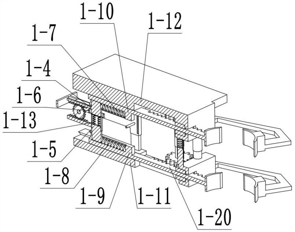
[0028] Combine below Figure 1-12 Describe this embodiment, an automatic fixed piling device, including a fixing device 1; a piling device 2;

specific Embodiment approach 2

[0030] Combine below Figure 1-12Describe this embodiment, this embodiment will further explain Embodiment 1, the described fixing device 1 includes a push rod 1-1; a rotating shaft 1-2; a gear 1-3; an upper slider 1-4; a lower slider 1-5; notch slider 1-6; upper spring 1-7; lower spring 1-8; lower rod 1-9; upper slider 1-10; lower base 1-11; upper base 1-12; tension Spring one 1-13; Gear two 1-14; Small cylinder one 1-15; Gear three 1-16; Small cylinder two 1-17; Lower power arm one 1-18; Lower power arm two 1-19; Lower power Arm three 1-20; Turn button 1-21; Rotating shaft two 1-22; Pinion 1-23; Vertical tooth 1-24; Tension spring two 1-25; Vertical pipe 1-26; Small cylinder three 1-27; Upper power arm one 1-28; upper power arm two 1-29; upper power arm three 1-30, both ends of the rotating shaft one 1-2 are fixedly connected with the push rod 1-1, and the rotating shaft one 1-2 is connected with the gear one 1 -3 rotating connection, gear one 1-3 is connected with upper s...

specific Embodiment approach 3

[0033] Combine below Figure 1-12 Illustrate this embodiment, this embodiment will further explain Embodiment 1, described piling device 2 comprises fixed boss 2-1; Motor 2-2; Runner 2-3; Gear four 2-4; Motor slider 2 -5; cylinder three 2-6; heterosexual wheel 2-7; vertical bar 2-8; left groove 2-9; round wheel 2-10; gear five 2-11; Gravity column 2-14; Motor notch 2-15, motor 2-2 is fixedly connected with runner 2-3, runner 2-3 is connected with gear four 2-4, motor 2-2 is connected with motor slide block 2 -5 is fixedly connected, gear four 2-4 is fixedly connected with cylinder three 2-6, fixed boss 2-1 is rotationally connected with cylinder three 2-6, cylinder three 2-6 is fixedly connected with opposite sex wheel 2-7, left groove 2-9 is arranged on the vertical rod 2-8, the opposite sex wheel 2-7 is connected with the left groove 2-9, the right groove 2-13 is arranged on the vertical rod 2-8, and the round wheel 2-10 is connected with the right groove 2-9. 13 is mating...


PUM


Abstract

The invention relates to the field of buildings, in particular to an automatic fixing piling device. The automatic fixing piling device can fix timber piles with uneven thickness and adjust the fixed height and the speed and the height of piling, so that the striking force and the striking frequency are adjusted. The automatic fixing piling device comprises a fixing device, a piling device and a lifting device. Timber piles with different thicknesses can be fixed through rotation of a first gear; the height of upper and lower power arms can be adjusted by rotating a knob, so that timber piles with different heights are fixed; the rotating speed of a special-shaped wheel and the rotating speed of a round wheel can be changed by adjusting the position of a motor in a motor notch, thus the lifting and falling speed of a vertical rod and a gravity column is changed, and the timber pile beating frequency is changed; and the height of the gravity column can be adjusted by rotating a lifting knob, so that the piling height is changed, and the piling strength is further changed.

Description

technical field [0001] The invention relates to the construction field, in particular to an automatic fixed piling device. Background technique [0002] The piling device is a common construction machine, but the general piling device cannot fix piles of different thicknesses, and its function is relatively single. Contents of the invention [0003] The purpose of the present invention is to provide an automatic fixed piling device, which can fix wooden piles with uneven thickness; can adjust the fixed height; can adjust the speed and height of piling, thereby adjusting the force and frequency of striking. [0004] The purpose of the present invention is achieved through the following technical solutions: [0005] An automatic fixed piling device, comprising a fixing device; a piling device; a lifting device, the fixing device is connected with the piling device, and the piling device is connected with the lifting device. [0006] As a further optimization of the technic...

Claims


Application Information

Patent Timeline
IPC IPC(8): E02D7/16E02D7/14E02D13/00
CPCE02D7/14E02D7/165E02D13/00
Inventor 张树文
Owner 张树文
Learn More