Twist drill with rake angle correction and its processing method
A processing method and twist drill technology, which is applied in twist drills, metal processing equipment, drilling/drilling equipment, etc., can solve the problems that the difference in the contour of the grinding wheel cannot be too large, it is unfavorable for the mass production of twist drills, and the twist drills cannot be used. Achieve the effects of shortening processing time, increasing sharpness, and reducing contact area
- Summary
- Abstract
- Description
- Claims
- Application Information
AI Technical Summary
Problems solved by technology
Method used
Image
Examples
Embodiment 1
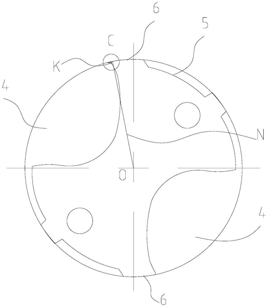
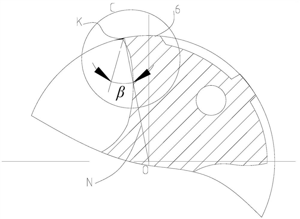
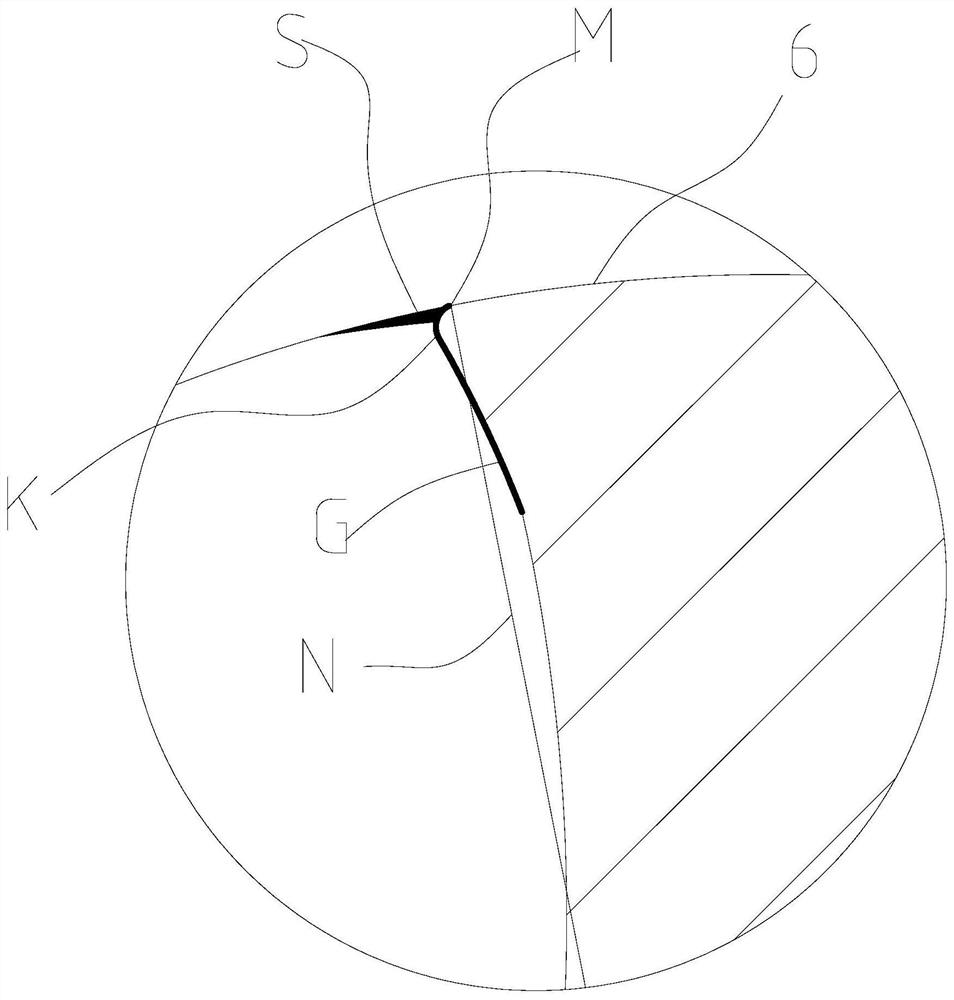
[0039] like Figure 5 to Figure 9 As shown, the twist drill with rake angle correction in this embodiment includes a cutting portion 1 and a shank portion 2. The front end of the cutting portion 1 is provided with a drill tip 3, and the cutting portion 1 is provided with two extending from the drill tip 3 to the shank portion. 2, the part of the cutting part 1 between the two helical chip flutes 4 constitutes a blade 5, in the rotational cutting direction of the twist turn ( Image 6 The arrow E) in the middle, the front end of the blade 5 is provided with a main land 6, the main land 6 is a circumferential cutting edge, and the drill tip 3 is an end face cutting edge. In the section perpendicular to the cutting portion 1, the helical chip flute 4 is connected with the main land 6 through a rake angle correction surface 7, and the connection line between the front end point M of the main land 6 and the center O of the blade 5 is a line N, The rake angle correction surface 7 i...
Embodiment 2
[0048] The processing method of the twist drill of the present embodiment is used to process the twist drill of embodiment 1, and the method comprises the following steps:
[0049] S1. Grind the spiral chip flute 4 of the twist drill with a coarse-grained forming grinding wheel. At this time, there is a sharp angle P between the spiral chip flute 4 and the main land 6;
[0050] S2. Use a polishing brush to polish the spiral chip flute 4 until it reaches the Ra0.1 mirror surface precision grinding effect. At this time, the sharp corner P is ground into a rounded corner K by the polishing brush;
[0051] S3. Use a fine-grained grinding wheel to grind the fillet K, so that the fillet K protruding relative to the line N becomes a concave rake angle correction surface 7 .
[0052] In this embodiment, in step S2, the polishing brush checks the spiral chip flute 4 twice. If the spiral chip flute 4 achieves the R0.1 mirror surface precision grinding effect, the polishing is stopped, a...
PUM
 Abstract
Description
Claims
Application Information
 - R&D
- Intellectual Property
- Life Sciences
- Materials
- Tech Scout
- Unparalleled Data Quality
- Higher Quality Content
- 60% Fewer Hallucinations
Browse by: Latest US Patents, China's latest patents, Technical Efficacy Thesaurus, Application Domain, Technology Topic, Popular Technical Reports.
© 2025 PatSnap. All rights reserved.Legal|Privacy policy|Modern Slavery Act Transparency Statement|Sitemap|About US| Contact US: help@patsnap.com


