
Chemical moving target monitoring method based on optical flow and momentum method

A moving target and momentum method technology, which is applied in the field of chemical moving target monitoring based on optical flow and momentum method, can solve the problems of high algorithm complexity of optical flow method, camera shake, and large influence of light noise, etc., to achieve system acceleration function, improve the accuracy and speed, and the effect of strong robustness

Active Publication Date: 2021-04-02
中船重工(武汉)凌久高科有限公司
View PDF4 Cites 0 Cited by
  • Summary
  • Abstract
  • Description
  • Claims
  • Application Information

AI Technical Summary

Problems solved by technology

However, in practical applications, when the complexity and variability of the external environment do not meet the constraints of the optical flow field, the optical flow field cannot be solved correctly; in addition, the algorithm complexity of the optical flow method is high, and it is used for motion detection. Poor real-time performance
[0007] Chemical moving targets have problems such as various colors and shapes, complex and changeable scenes, great influence of light noise, and camera shake. The current chemical moving targets only detect a specific scene such as a tank farm, and cannot adapt to complex and changeable scenes such as vibration. Screens, hot boxes, cold boxes, outlets, etc., so there is an urgent need for a general, efficient, and automatic moving target detection method

Method used


Image

  • Chemical moving target monitoring method based on optical flow and momentum method
  • Chemical moving target monitoring method based on optical flow and momentum method
  • Chemical moving target monitoring method based on optical flow and momentum method

Examples


Embodiment Construction

[0043] In order to make the object, technical solution and advantages of the present invention clearer, the present invention will be further described in detail below in conjunction with the accompanying drawings and embodiments. It should be understood that the specific embodiments described here are only used to explain the present invention, not to limit the present invention. In addition, the technical features involved in the various embodiments of the present invention described below can be combined with each other as long as they do not constitute a conflict with each other.

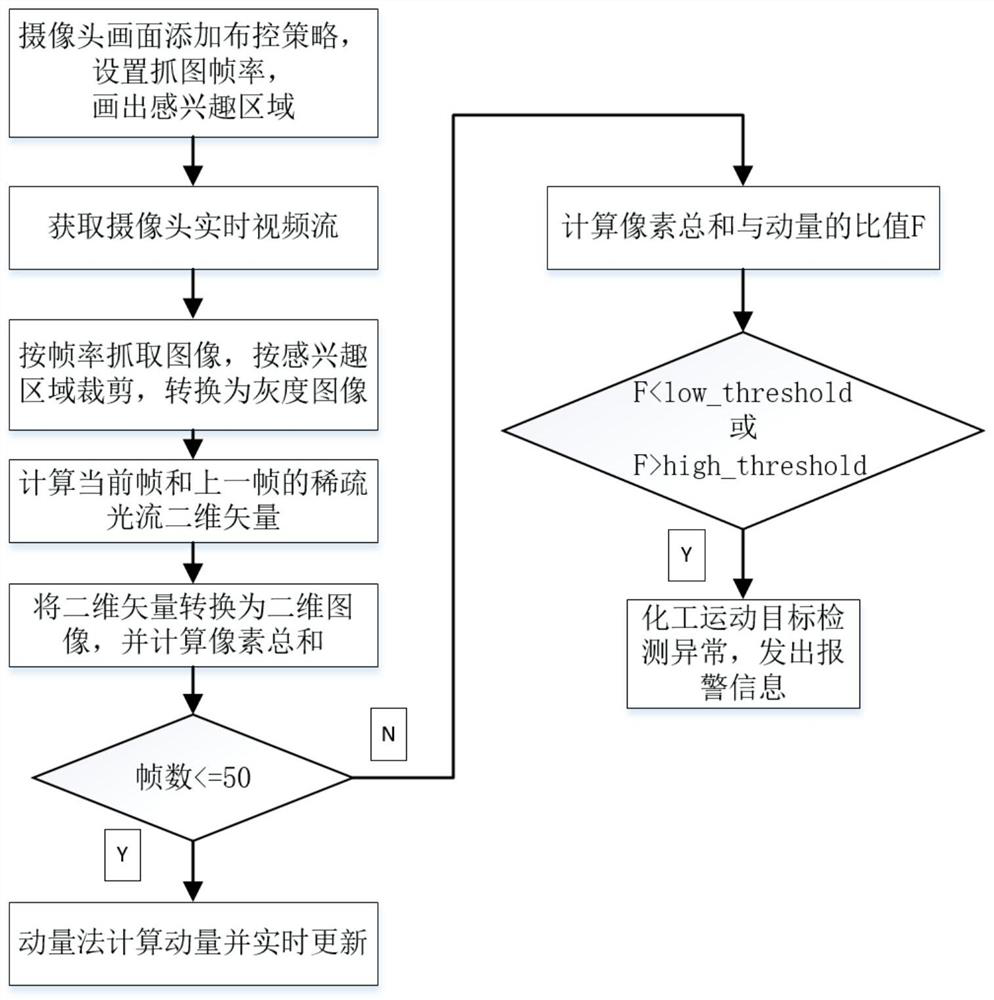
[0044] Such as figure 1 As shown, the embodiment of the present invention provides a method for monitoring chemical moving objects based on optical flow and momentum methods, wherein the chemical moving objects may include styrene-butadiene rubber, polystyrene, butadiene rubber, etc. in the production workshop of an ethylene plant. The method includes the following steps:

[0045] Step 1, interc...


PUM


Abstract

The invention provides a chemical moving target monitoring method based on an optical flow and momentum method. The chemical moving target monitoring method comprises the following steps: interceptinga frame of camera image; acquiring a real-time video stream shot by a camera; circularly capturing an image according to a set image capturing frame rate, cutting the image according to a region of interest, and converting the cut image into a grayscale image; calculating sparse optical flow two-dimensional vectors of the grayscale images obtained by the current frame and the previous frame; converting the two-dimensional vector into a two-dimensional image, and calculating a pixel sum S in the two-dimensional image; judging whether the frame number is less than or equal to a preset target threshold of the captured frame number, if so, calculating the momentum Mt of the current frame by using a momentum method, and updating the momentum Mt in real time; and if the frame number exceeds thepreset target threshold of the captured frame number, calculating the ratio of the obtained pixel sum S to the momentum Mt, and judging whether the moving target detection is abnormal or not according to the ratio. According to the invention, the monitoring efficiency and reliability can be improved, and an important guarantee is provided for safe operation and management of chemical product production.

Description

technical field [0001] The invention relates to the technical field of moving target detection, in particular to a method for monitoring a chemical moving target based on optical flow and momentum methods. Background technique [0002] The production process of chemical products is complicated. In the production process, due to the high water content of some materials, the high viscosity of some, and the fine particle size of some, and the unreasonable structure of the silo, etc., there are often breakages when the material is discharged. The material phenomenon makes the feeding equipment unable to continuously and normally feed materials. If a problem occurs in one process, it will affect a series of subsequent production processes, seriously affecting the normal production of the workshop, and there are certain safety hazards. [0003] The assembly line production of chemical products is the category of moving object detection. Moving object detection refers to the proce...

Claims


Application Information

Patent Timeline
IPC IPC(8): G06T7/20
CPCG06T7/20G06T2207/10016G06T2207/20132
Inventor 武玉杰杨志祥肖芳丁又华皮辉蔡烨彬葛育波刘康立黄志鹏吴刘瑱程欣王珍闵张张刘如来
Owner 中船重工(武汉)凌久高科有限公司
Learn More