


Quick Research
Generate reliable direction feasibility study reports for your R&D in just a few steps.

Technical Q&A
Discover and master advanced knowledge NOW. Basics, ideas, possibilities, all at once.

Find Solutions
As an expert in R&D theories, this can generate solutions to your technical problems instantly.

Evaluate Feasibility
Analyze your overall solution with one click, know your potential R&D risks in advance.

Monitor Landscape
Get weekly tech updates, stay abreast of the latest tech innovations and key insights.
Power shaft system bearing fault detection method and system
A fault detection and power shafting technology, applied in the field of signal processing and deep learning, can solve problems such as abnormal mechanical equipment, casualties, and it is difficult to take into account the time-frequency characteristics of non-stationary signals.
- Summary
- Abstract
- Description
- Claims
- Application Information
AI Technical Summary
Problems solved by technology
Method used
Image

Examples
Embodiment 1
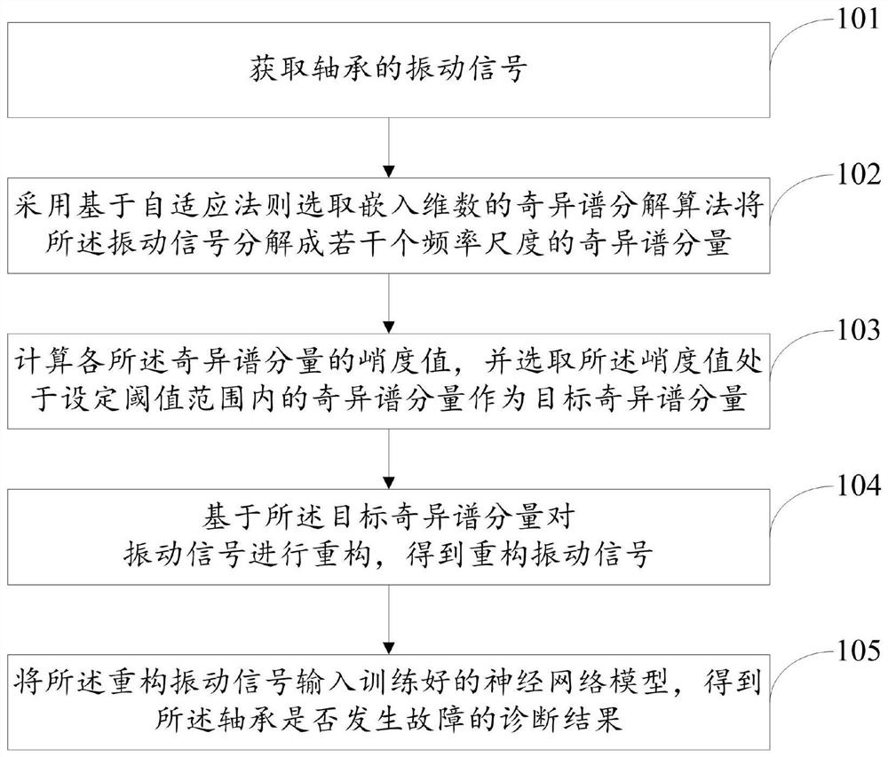
[0050] see figure 1 , the present embodiment provides a power shaft bearing fault detection method, the method includes the following steps:
[0051] Step 101: Obtain the vibration signal of the bearing.
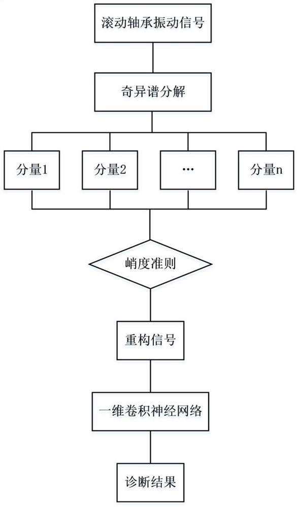
[0052] Step 102: Using singular spectrum decomposition to decompose the vibration signal into singular spectral components of several frequency scales. The specific decomposition process can be as follows:
[0053] (1) Construct a new trajectory matrix. Suppose x(n) is a time series, its embedding dimension is M, and the data length is N, and x(n) is constructed into a matrix X of size M×N, then the i-th row of matrix X can be expressed as x i =(x(i),...,x(N),x(1),...,x(i-1)), where i=1,...,M, namely
[0054] (2) Adaptively select the embedding dimension size M. The singular spectrum decomposition adopts the adaptive law to select the embedding dimension M at the jth iteration, and the specific process can be as follows:
[0055] a. Calculate the remaining component ...
Embodiment 2
[0095] see Figure 7 , the present embodiment provides a power shaft bearing fault detection system, the system includes:
[0096] A vibration signal acquisition module 701, configured to acquire a vibration signal of the bearing;
[0097] A singular spectrum decomposition module 702, configured to decompose the vibration signal into singular spectrum components of several frequency scales by employing singular spectrum decomposition;
[0098] A screening module 703, configured to calculate the kurtosis value of each of the singular spectral components, and select the singular spectral component whose kurtosis value is within a set threshold range as the target singular spectral component;
[0099] A reconstruction module 704, configured to reconstruct the vibration signal based on the target singular spectral component to obtain a reconstructed vibration signal;
[0100] Diagnosis module 705, configured to input the reconstructed vibration signal into the trained neural net...
PUM
 Abstract
Description
Claims
Application Information
 - R&D Engineer
- R&D Manager
- IP Professional
- Industry Leading Data Capabilities
- Powerful AI technology
- Patent DNA Extraction
Browse by: Latest US Patents, China's latest patents, Technical Efficacy Thesaurus, Application Domain, Technology Topic, Popular Technical Reports.
© 2024 PatSnap. All rights reserved.Legal|Privacy policy|Modern Slavery Act Transparency Statement|Sitemap|About US| Contact US: help@patsnap.com