
Electric vehicle braking system and method

A brake system and electric vehicle technology, applied in bicycle accessories, bicycle brakes, audio signals, etc., can solve the problems of hidden brake failure, frustration, and inconvenience for users, so as to improve the reliability of brakes, improve the riding experience, The effect of convenient maintenance in the later period

Pending Publication Date: 2021-04-02
新大洲本田摩托(苏州)有限公司
View PDF0 Cites 0 Cited by
  • Summary
  • Abstract
  • Description
  • Claims
  • Application Information

AI Technical Summary

Problems solved by technology

Therefore, when the brake lever is released but the switch is not disconnected, there will be a problem that the whole vehicle cannot be driven by turning the accelerator handle
Therefore, you will feel a sense of frustration when you start on a flat road, and it may cause the car to slip when you start on a slope, and it will be dangerous if it is serious.
[0004] In the existing technical solutions, most of them lack the self-testing process of electric vehicle brakes, and there is a hidden danger of brake failure; in some technical solutions, there is a process of power-on detection and braking. User inconvenience

Method used

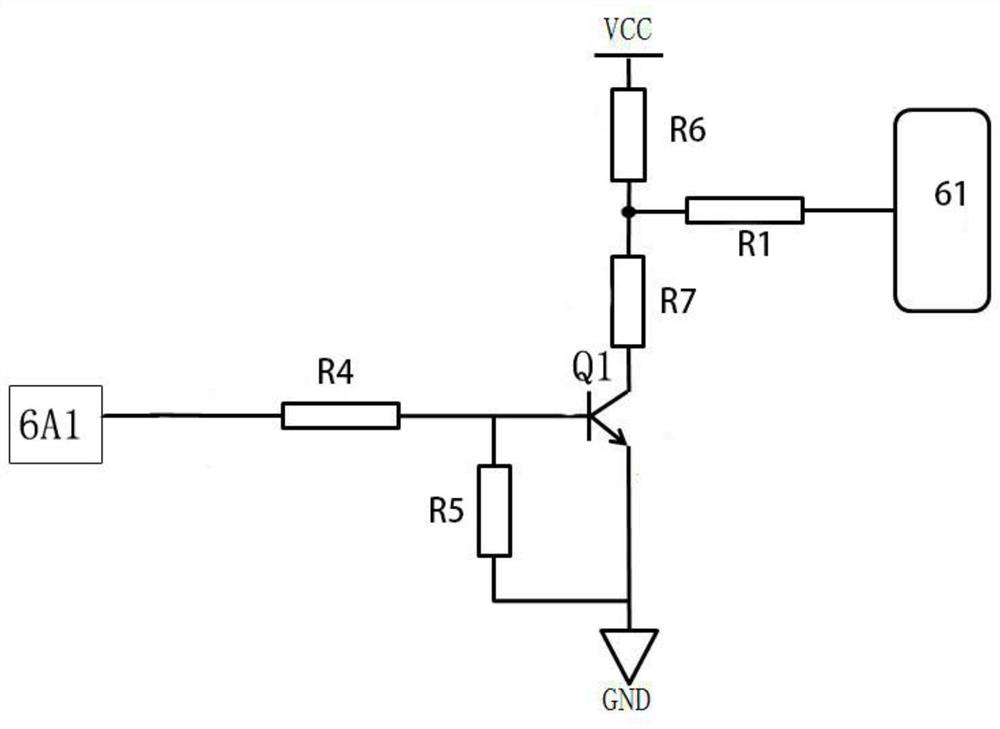
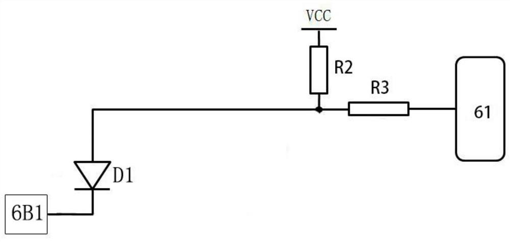

Image

  • Electric vehicle braking system and method
  • Electric vehicle braking system and method
  • Electric vehicle braking system and method

Examples


Embodiment Construction

[0056] The present invention will be described in detail below in conjunction with the accompanying drawings and specific embodiments. The present invention is not limited to this embodiment, and other embodiments may also belong to the scope of the present invention as long as they conform to the gist of the present invention.

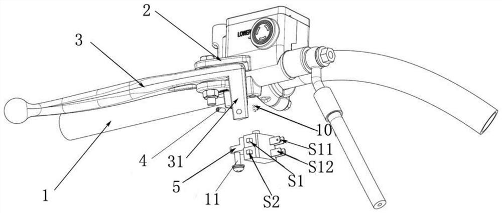
[0057] In a preferred embodiment of the present invention, based on the above-mentioned problems existing in the prior art, an electric vehicle braking device is now provided, such as figure 1 shown, including:

[0058] a base 2;

[0059] A brake handle 3, pivotally hinged on the base 2, used to drive the mechanical brake device, the end of the brake handle 3 near the hinge point is provided with a protrusion 31;

[0060] A switch assembly 5 is fixed on the lower end of the base 2 and interferes with the protrusion 31. The switch assembly 5 includes:

[0061] A first switch S1, connected in series with the brake circuit of the electric vehicle driv...


PUM


Abstract

The invention provides an electric vehicle braking system and method, and relates to the technical field of electric vehicle control. The electric vehicle braking system includes: a base; a brake handle which is hinged to the base in a pivoted mode and used for driving the mechanical brake device, and a protruding part is arranged at the end, close to the hinge point, of the brake handle; a switchassembly, wherein the switch assembly is fixedly arranged at the lower end of the base and forms interference with the protruding part, and the switch assembly comprises a first switch which is connected to a brake loop of the electric vehicle driving controller in series; a second switch which is connected to a brake loop of the electric vehicle driving controller in series; and an electric vehicle driving controller which is used for respectively controlling the electric vehicle driving controller to enter a first brake state and a second brake state according to the first switch signal andthe second switch signal so as to carry out brake self-detection and control the running state of the driving motor. The riding feeling of hill starting and electronic braking is improved, and it isguaranteed that a driver is safer in the whole vehicle driving process; and the braking reliability is improved, and meanwhile, the brake device has the advantages of being simple in structure and convenient to maintain in the later period.

Description

technical field [0001] The invention relates to the technical field of electric vehicle control, in particular to an electric vehicle braking system and method. Background technique [0002] Electric vehicles are a convenient and green means of transportation, and have become an important part of many people's lives. [0003] Most of the electric vehicles on the market adopt the method of sharing the brake light control switch and the brake signal switch. In this way, when the brake handle is pulled, the brake light and the brake signal are triggered at the same time, and only when the brake handle is released to turn off the switch, the brake signal will be released. Therefore, when the brake handle is released but the switch is not disconnected, there will be a problem that the vehicle cannot be driven by turning the throttle handle. Therefore, when starting on a flat road, you will feel a sense of frustration, and starting on a slope may cause the car to slip, and in se...

Claims


Application Information

Patent Timeline
Patent Type & Authority Applications(China)
IPC IPC(8): B62L3/02B62L1/00B62J6/045B62J3/10B62J3/12
CPCB62L1/00B62L3/026B62J3/10B62J3/12B62J6/045
Inventor 丁建国王旭东宋玉龙
Owner 新大洲本田摩托(苏州)有限公司
Learn More