Bidirectional DC-DC converter and uninterruptible power supply comprising same

A DC-DC and converter technology, applied in the field of uninterruptible power supply, can solve the problems of large turn-on loss and turn-off loss switching loss of switching transistors, low power conversion efficiency, high cost, etc., to reduce switching loss and reduce overall cost , to avoid the effect of loop current

Active Publication Date: 2021-03-30
SANTAK ELECTRONICS SHENZHEN
View PDF18 Cites 0 Cited by
  • Summary
  • Abstract
  • Description
  • Claims
  • Application Information

AI Technical Summary

Problems solved by technology

[0003] However, when the switch transistor in the bidirectional DC-DC converter is controlled to be turned on or off, the voltage across the switch transistor is not equal to 0, that is, the turn-on and turn-off process is not performed at zero voltage, so the The switching transistor has a large turn-on loss and turn-off loss (ie switching loss) in the working state, resulting in a low switching frequency and low power conversion efficiency of the bidirectional DC-DC converter
In addition, when the switching frequency of the bidirectional DC-DC converter is low, the inductor in the bidirectional DC-DC converter should use an inductor with a larger inductance value, that is, an inductor with a larger volume and a higher cost. This bidirectional DC-DC converter has low power density and high cost

Method used


Image

  • Bidirectional DC-DC converter and uninterruptible power supply comprising same
  • Bidirectional DC-DC converter and uninterruptible power supply comprising same
  • Bidirectional DC-DC converter and uninterruptible power supply comprising same

Examples


Embodiment Construction

[0042] In order to make the object, technical solution and advantages of the present invention clearer, the present invention will be further described in detail below through specific embodiments in conjunction with the accompanying drawings.

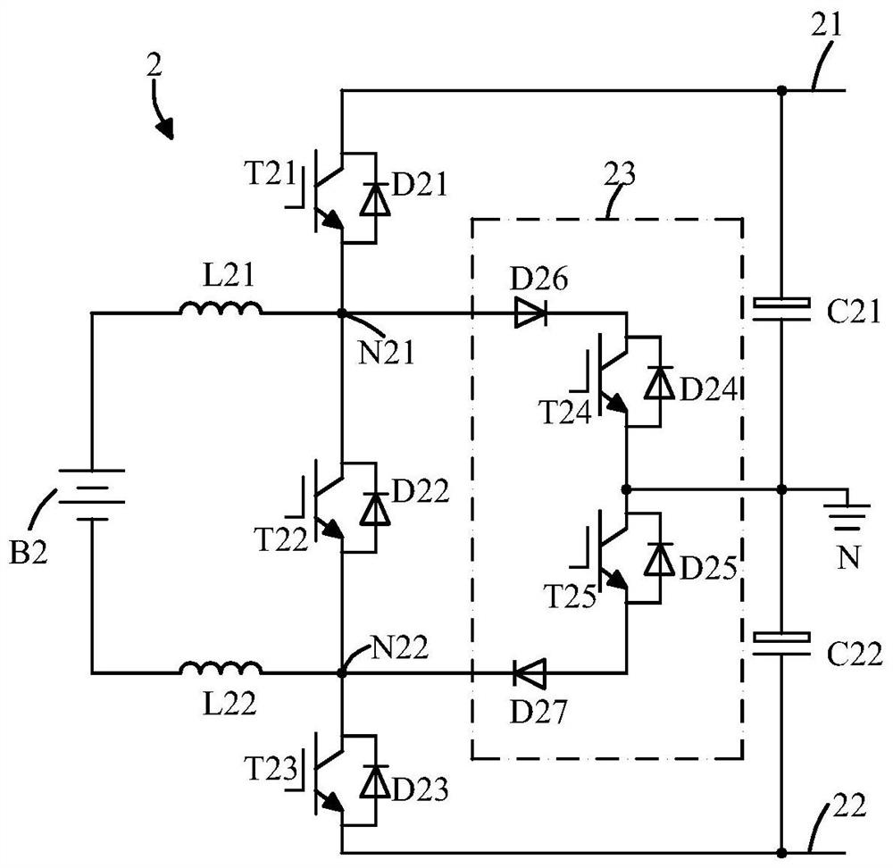
[0043] figure 1 is a circuit diagram of a bidirectional DC-DC converter according to the first embodiment of the present invention. Such as figure 1 As shown, the bidirectional DC-DC converter 2 includes an insulated gate bipolar transistor T21 with an antiparallel diode D21 and an insulated gate bipolar transistor with an antiparallel diode D22 connected in sequence between the positive DC bus 21 and the negative DC bus 22. A bipolar transistor T22, an insulated gate bipolar transistor T23 with an antiparallel diode D23, wherein the insulated gate bipolar transistor T21 is connected with the insulated gate bipolar transistor T22 to form a first node N21, the insulated gate bipolar transistor The transistor T22 is connected with the ...


PUM


Abstract

The invention provides a bidirectional DC-DC converter and an uninterruptible power supply comprising the same. The bidirectional DC-DC converter is provided with a first switching transistor with a first anti-parallel diode, a second switching transistor with a second anti-parallel diode, and a third switching transistor with a third anti-parallel diode, wherein the first switching transistor, the second switching transistor and the third switching transistor are sequentially connected between a positive direct-current bus and a negative direct-current bus; and the second switching transistoris respectively connected with the first switching transistor and the third switching transistor to form a first node and a second node; a switching transistor assembly including a plurality of switching transistors connected in series and connected in parallel with the second switching transistor; a first inductor connected between the first node and the positive electrode of a rechargeable battery and/or a second inductor connected between the second node and the negative electrode of the rechargeable battery; and a control device which is used for controlling the switching transistor assembly to be in an on state in the process of changing the switching state of the second switching transistor. The bidirectional DC-DC converter provided by the invention has lower switching loss.

Description

technical field [0001] The invention relates to a DC-DC converter, in particular to a bidirectional DC-DC converter and an uninterruptible power supply including the same. Background technique [0002] A bidirectional DC-DC converter is a device that realizes the bidirectional flow of DC power, and is mainly used in uninterruptible power supplies. The bidirectional DC-DC converter usually adopts the classic buck chopper (Buck) and boost chopper (Boost) circuit topology, and has buck and boost bidirectional conversion functions. [0003] However, when the switch transistor in the bidirectional DC-DC converter is controlled to be turned on or off, the voltage across the switch transistor is not equal to 0, that is, the turn-on and turn-off process is not performed at zero voltage, so the The switching transistor has large turn-on loss and turn-off loss (ie switching loss) in the working state, resulting in a low switching frequency and low power conversion efficiency of the b...

Claims


Application Information

Patent Timeline
Patent Type & Authority Applications(China)
IPC IPC(8): H02M3/158H02J9/06
CPCH02M3/158H02J9/06
Inventor 胡高宏曹磊刘丹龙秀山
Owner SANTAK ELECTRONICS SHENZHEN
Why Eureka
Try Eureka