
Chip 3D morphology preparation method

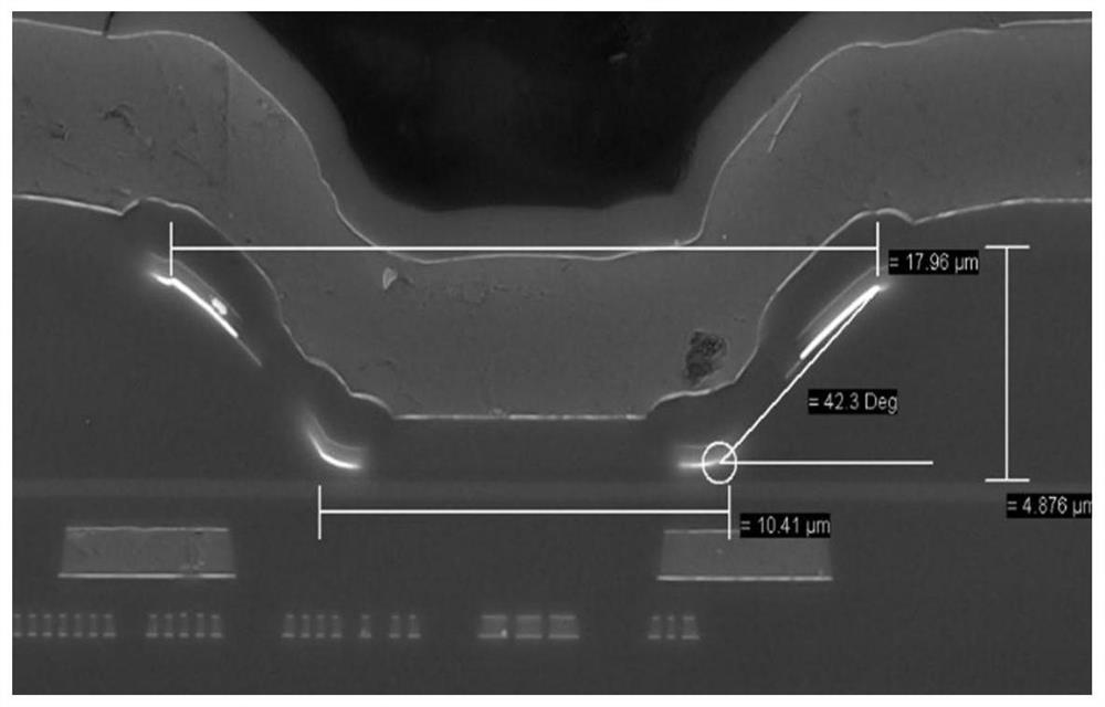
A 3D, topography technology, applied in the manufacture/processing of magnetic field controlled resistors, electromagnetic devices, etc., can solve the problems of small slope angle and large graphic size, achieve good slope surface and slope, and improve performance.

Active Publication Date: 2021-03-30
QST CORP
View PDF2 Cites 0 Cited by
  • Summary
  • Abstract
  • Description
  • Claims
  • Application Information

AI Technical Summary

Problems solved by technology

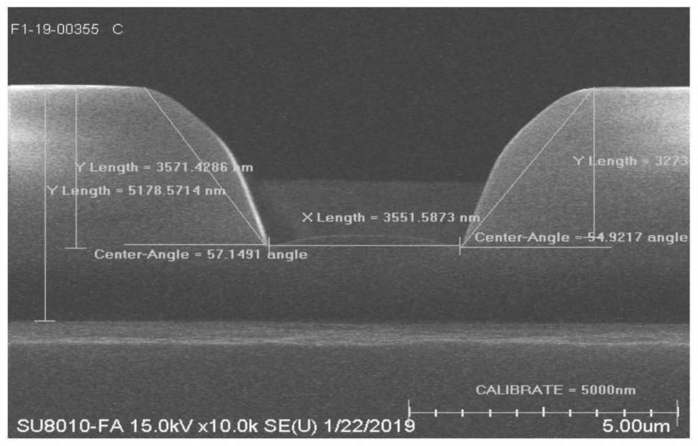
The disadvantage is that the graph size is large and the slope angle is small (such as figure 2 shown)

Method used


Image

  • Chip 3D morphology preparation method
  • Chip 3D morphology preparation method
  • Chip 3D morphology preparation method

Examples


Embodiment Construction

[0046] Preferred embodiments of the present invention will be described in detail below in conjunction with the accompanying drawings.

[0047] In order to further understand the present invention, the preferred embodiments of the present invention are described below in conjunction with examples, but it should be understood that these descriptions are only to further illustrate the features and advantages of the present invention, rather than limiting the claims of the present invention.

[0048] The description in this part is only for several typical embodiments, and the present invention is not limited to the scope of the description of the embodiments. The mutual replacement of the same or similar prior art means and some technical features in the embodiments is also within the scope of the description and protection of the present invention.

[0049] The description of the steps in each embodiment in the specification is only for convenience of description, and the imple...


PUM


Abstract

The invention discloses a chip 3D morphology preparation method, and the method comprises the steps: growing a first dielectric material on a substrate, and forming a first dielectric material layer;growing a second dielectric material on the first dielectric material layer to form a second dielectric material layer, the second dielectric material layer comprising at least two second dielectric material layer units; different second dielectric material layer units have set intervals to form partitions with the set intervals; a high-density plasma layer with set gradient and height is formed by utilizing the process characteristic that high-density plasma is deposited and etched at the same time; and silicon oxide is grown on the high-density plasma layer to form a silicon oxide layer. According to the chip 3D morphology preparation method provided by the invention, the prepared product has better slope surface and gradient, and the performance of the product is improved.

Description

technical field [0001] The invention belongs to the technical field of semiconductor preparation, and relates to a chip preparation method, in particular to a 3D shape preparation method. Background technique [0002] The AMR sensor chip can sense the change of the magnetic field according to the change of the resistance of the magnetoresistive bridge group. The AMR sensor chip is formed by sputtering a nickel-iron film on a silicon wafer. The nickel-iron films are arranged in the form of strips to form a planar linear array to increase the sensing magnetic field area of ​​the magnetoresistance. When an external magnetic field is applied to the nickel-iron film, the magnetic domain rotates and the spatial orientation is changed, the apparent resistance of the nickel-iron film line array changes, and the bridge voltage output changes synchronously. [0003] The single-chip integrated three-axis AMR chip needs to simultaneously manufacture the X / Y axis of the sensing plane a...

Claims


Application Information

Patent Timeline
Patent Type & Authority Applications(China)
IPC IPC(8): H01L43/08H01L43/12H10N50/10H10N50/01
CPCH10N50/01H10N50/10Y02P70/50
Inventor 徐伟肖勇陈逸清
Owner QST CORP
Learn More