
Civil engineering brick laying device

A civil engineering and brick laying technology, applied in the field of civil engineering brick laying devices, can solve the problems of prolonging the construction period, reducing the construction efficiency, easy to collapse, etc., and achieving the effects of ensuring life safety, ensuring stability and reducing workload

Inactive Publication Date: 2021-03-30
深圳市文立业贸易有限公司
View PDF6 Cites 0 Cited by
  • Summary
  • Abstract
  • Description
  • Claims
  • Application Information

AI Technical Summary

Problems solved by technology

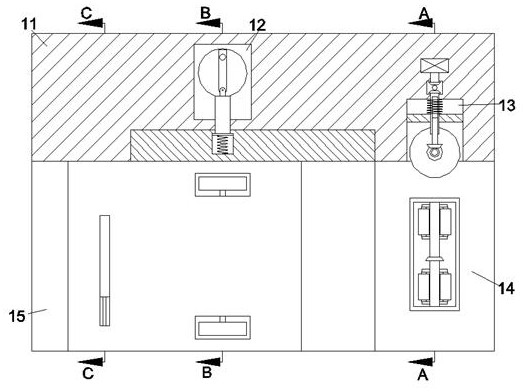
[0002] When building a construction project, the most basic thing is the bricklaying project. When the workers are laying the bricks, the mortar on the surface of the bricks cannot be evenly distributed, and the pressure exerted on the bricks cannot be uniform, which will make the finished bricks There are ups and downs in the height of the blocks, which will cause uneven force on the built-up wall and easy collapse, which will threaten the life safety of construction workers, reduce construction efficiency, prolong the construction period, and workers It is also necessary to scrape off the excess mortar between the brick joints, thereby increasing the workload of the workers. A civil engineering bricklaying device set forth in the present invention can solve the above problems

Method used


Image

  • Civil engineering brick laying device
  • Civil engineering brick laying device
  • Civil engineering brick laying device

Examples


Embodiment Construction

[0017] Combine below Figure 1-5 The present invention is described in detail, wherein, for the convenience of description, the orientations mentioned below are defined as follows: figure 1 The up, down, left, right, front and back directions of the projection relationship itself are the same.

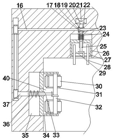
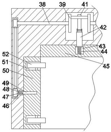
[0018] A civil engineering bricklaying device according to the present invention includes a box body 11, and a mud scraping chamber 15 with an opening facing left and facing down is provided inside the box body 11, and the upper end wall of the mud scraping chamber 15 can be set by sliding back and forth There is a pressing side plate 50 symmetrical front and back about the symmetrical center of the mud scraping chamber 15, and a collecting chamber 55 with an opening close to the symmetrical center of the mud scraping chamber 15 is arranged inside the pressing side plate 50, and the collecting chamber 55 is provided with a transmission block chamber 70 on the side away from the symmet...


PUM


Abstract

The invention discloses a civil engineering brick laying device. The civil engineering brick laying device comprises a box body, wherein a mud scraping cavity with a leftward opening and a downward opening is formed in the box body; pressing side plates which are symmetrical front and back relative to the symmetrical center of the mud scraping cavity are arranged on the upper end wall of the mud scraping cavity in a front-back sliding mode; a collecting cavity with an opening close to one side of the symmetrical center of the mud scraping cavity is formed in each pressing side plate; a transmission clamping block cavity is formed in one side, far away from the symmetrical center of the mud scraping cavity, of each collecting cavity; a switching cavity is formed in the upper side of each transmission clamping block cavity in a communicating mode; and a mud scraping device is arranged in each collecting cavity. According to the civil engineering brick laying device, the orientation of bricks coated with mortar is adjusted, so that the laid bricks can be ensured to be at the same height, the stability of the laid wall body is ensured, the life safety of workers during construction isensured, the mortar which is excessive between brick joints on the upper side and the lower side is scraped and recycled, and the scraping of the mortar by the workers is reduced.

Description

technical field [0001] The invention relates to the related fields of civil engineering, in particular to a civil engineering bricklaying device. Background technique [0002] When building a construction project, the most basic thing is the bricklaying project. When the workers are laying the bricks, the mortar on the surface of the bricks cannot be evenly distributed, and the pressure exerted on the bricks cannot be uniform, which will make the finished bricks There are ups and downs in the height of the blocks, which will cause uneven force on the built-up wall and easy collapse, which will threaten the life safety of construction workers, reduce construction efficiency, prolong the construction period, and workers It is also necessary to scrape off the extra mortar between the brick joints, thereby increasing the workload of the workers. A civil engineering bricklaying device set forth in the present invention can solve the above problems. Contents of the invention ...

Claims


Application Information

Patent Timeline
IPC IPC(8): E04G21/22
CPCE04G21/22
Inventor 路喜
Owner 深圳市文立业贸易有限公司
Learn More