Deformed steel bar quenching process and quenching equipment
A technology of quenching equipment and rebar, applied in quenching equipment, heat treatment equipment, manufacturing tools, etc., can solve the problems of rising coolant temperature, decreasing quenching efficiency of forgings, slowing down cooling rate of forgings, etc., to achieve the effect of uniform contact surface
- Summary
- Abstract
- Description
- Claims
- Application Information
AI Technical Summary
Problems solved by technology
Method used
Image
Examples
Embodiment 1
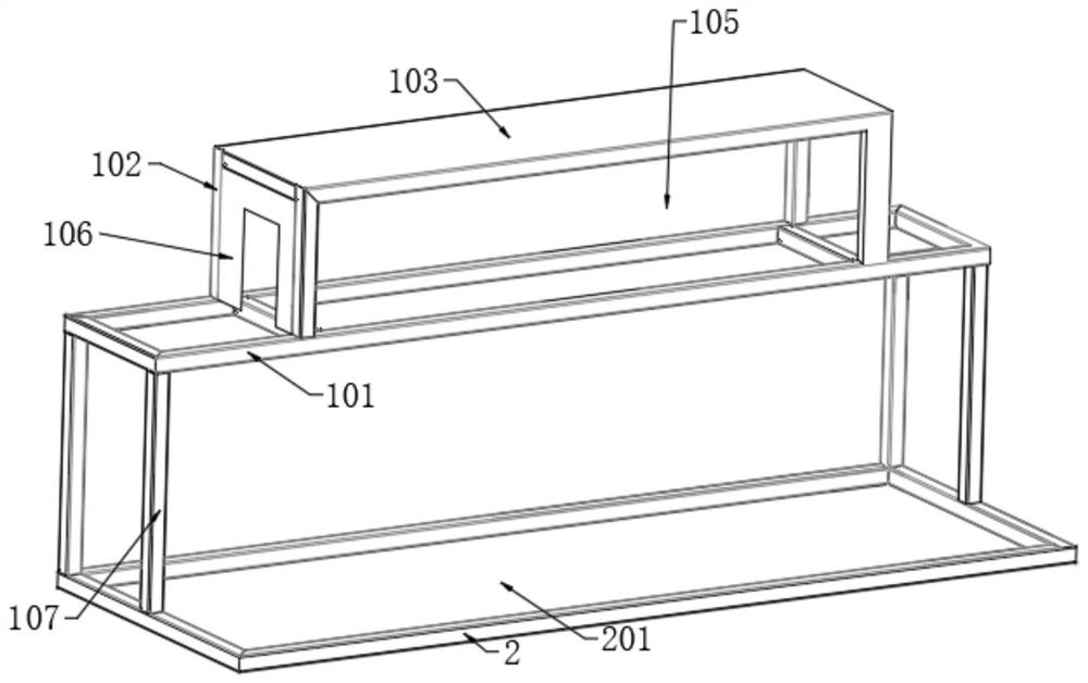
[0061] Such as figure 1 As shown, a threaded steel quenching device according to an embodiment of the present invention includes: a frame 1, a quenching inlet 3, a quenching outlet 4, a transmission device 5, a bottom plate 6, a liquid collection tank 7, a filtering device 8 and a supporting device 9 ;
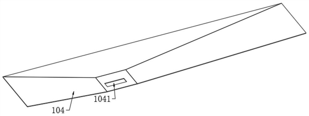
[0062] Among them, such as Figure 1-2 As shown, the frame 1 includes a rectangular frame 101, a pair of rectangular support frames 102 are vertically connected along the width direction between the rectangular frames 101, a top plate 103 is fixedly connected between the upper ends of a pair of rectangular support frames 102, and a guide rail is fixedly installed between the lower ends of the pair of rectangular support frames 102. The bottom plate 104 and the back are fixedly installed with a back plate 105, each rectangular support frame 102 is welded with a U-shaped outer sealing plate 106, and the four corners of the lower surface of the rectangular frame 101 are vertical...
Embodiment 2
[0077] Such as figure 1 As shown, the difference between this embodiment and Embodiment 1 is that a drive motor 203 is fixedly installed on the bottom frame 2 , and a drive sprocket 204 is coaxially sleeved on the output end of the drive motor 203 .
[0078] By adopting the above technical solution, the drive motor 203 is provided as the power output of the transmission device 5, so that the transmission device 5 drives the forging to move forward.
Embodiment 3
[0080] Such as Figure 4 As shown, the difference between this embodiment and Embodiment 2 is that the transmission device 5 also includes a driving roller 502 and a driven roller 503, and the driving roller 502 and the driven roller 503 are all rotatably connected in each group of rotating shaft seats 501, and the driving Roller 502 and driven roller 503 are coaxially provided with a pair of driving pulleys 504, and a conveyor belt 505 is connected to rotate between the pair of driving pulleys 504. One side of driving roller 502 is coaxially sleeved with driven sprocket 506. The driving sprocket 506 is connected to the driving sprocket 204 through a motor chain 507 .
[0081] By adopting the above-mentioned technical scheme, start the driving motor 203, the output end of the driving motor 203 drives the driving sprocket 204 to rotate, because the driving sprocket 204 is connected with the driven sprocket 506 through the motor chain 507, so that the driven sprocket 506 drives ...
PUM
 Abstract
Description
Claims
Application Information
 - R&D
- Intellectual Property
- Life Sciences
- Materials
- Tech Scout
- Unparalleled Data Quality
- Higher Quality Content
- 60% Fewer Hallucinations
Browse by: Latest US Patents, China's latest patents, Technical Efficacy Thesaurus, Application Domain, Technology Topic, Popular Technical Reports.
© 2025 PatSnap. All rights reserved.Legal|Privacy policy|Modern Slavery Act Transparency Statement|Sitemap|About US| Contact US: help@patsnap.com


