
Synchronous three-axis attitude control magnetic levitation inertia actuating mechanism

A technology of three-axis attitude and actuators, which is applied in the field of space vehicles, can solve the problems of limiting system control accuracy, rotor turbine loss, system temperature rise, etc., and achieve the effect of high control torque accuracy, small loss, and small rotor eddy current loss

Active Publication Date: 2021-03-30
SHANGHAI AEROSPACE CONTROL TECH INST
View PDF6 Cites 0 Cited by
  • Summary
  • Abstract
  • Description
  • Claims
  • Application Information

AI Technical Summary

Problems solved by technology

This attitude control system requires at least three inertial actuators, resulting in an increase in system mass and power consumption; in addition, the frequent momentum exchange between each inertial actuator also limits the control accuracy of the system
[0004] In order to solve this problem, researchers in this technical field have done some research. For example, patent CN104143947A discloses an inertial actuator named "Inductive Reaction Momentum Ball System". Ball module, displacement detection and driving circuit, speed detection module and control system, wherein the reaction momentum ball module is composed of a spherical rotor and coils arranged around the spherical rotor, through the spherical rotor driven by the induction motor to realize the output of three-axis control torque target, and then achieve the purpose of completing the three-axis attitude control of the space vehicle through a single inertial actuator; however, the inductive reaction momentum ball system uses an induction motor to drive its rotor, resulting in serious loss of the rotor turbine, which not only increases the loss of the system, but also It will cause the temperature rise of the system, which is not conducive to its application

Method used


Image

  • Synchronous three-axis attitude control magnetic levitation inertia actuating mechanism
  • Synchronous three-axis attitude control magnetic levitation inertia actuating mechanism
  • Synchronous three-axis attitude control magnetic levitation inertia actuating mechanism

Examples


Embodiment Construction

[0040] The following will clearly and completely describe the technical solutions in the embodiments of the present invention with reference to the accompanying drawings in the embodiments of the present invention. Obviously, the described embodiments are only some, not all, embodiments of the present invention. Based on the embodiments of the present invention, all other embodiments obtained by persons of ordinary skill in the art without making creative efforts belong to the protection scope of the present invention.

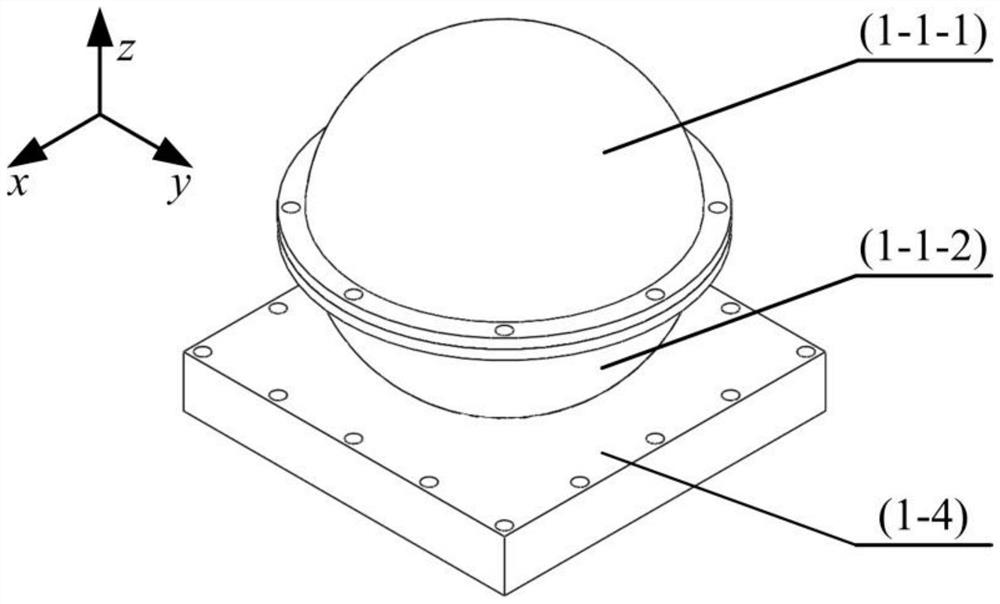
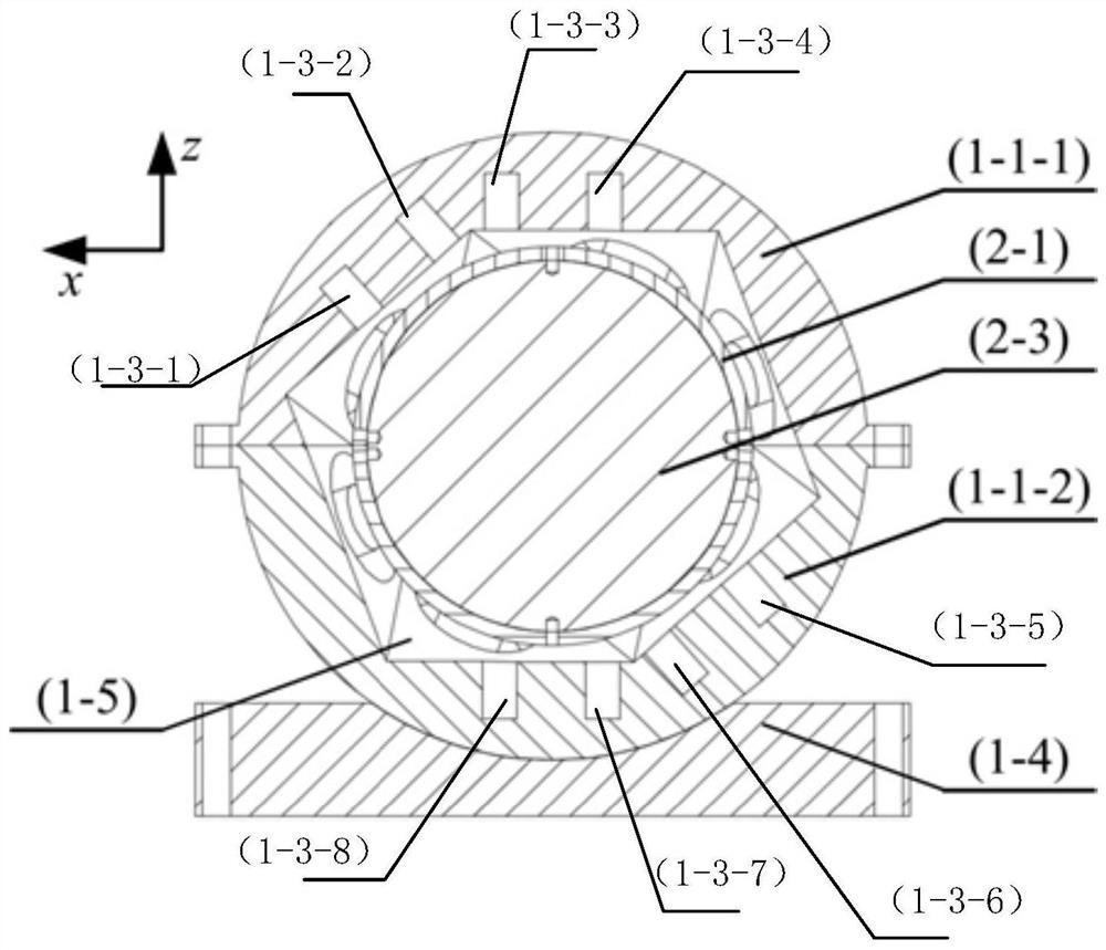
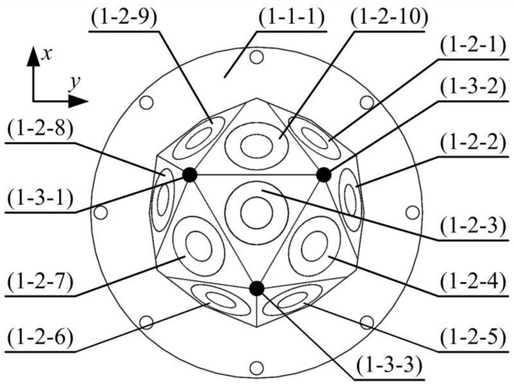
[0041] The present invention provides a synchronous three-axis attitude control magnetic levitation inertial actuator, including: a stator, a rotor, and a stator base 1-4.

[0042] Such as figure 1 , figure 2 , image 3 , Figure 4 As shown, in Embodiment 1 of the present invention, the stator includes two identical stator frames (respectively the first stator frame 1-1-1 and the second stator frame 1-1-2), 20 stator frames Windings (respectively the firs...


PUM


Abstract

The invention provides a synchronous three-axis attitude control magnetic levitation inertia actuating mechanism. The synchronous three-axis attitude control magnetic levitation inertia actuating mechanism comprises a stator, a rotor and a stator base, wherein the stator comprises two stator frames which form a hollow first spherical structure in an embracing manner; a plurality of stator windingsand a plurality of sensors are embedded into the inner wall of the stator frame; the rotor comprises two rotor frames which are combined to form a hollow second spherical structure; a plurality of rotor permanent magnets and a rotor iron core, the rotor permanent magnets are uniformly distributed and embedded in the outer surface of the rotor iron core, the rotor permanent magnets and the rotor iron core are integrally and fixedly connected to form a third spherical structure, and the third spherical structure is fixedly embedded in the second spherical structure; the rotor is located in thecavity of the stator frame, an air gap exists between the stator and the rotor, and no mechanical contact exists among the rotor, the stator and the stator winding. The mechanism is advantaged in thatthe rotor can rotate around any axis in the three-dimensional space, three-axis attitude control over the spacecraft is achieved, control precision is high, losses are small, and lubrication is not needed.

Description

technical field [0001] The invention relates to the technical field of space vehicles, in particular to a synchronous three-axis attitude control magnetic suspension inertial actuator. Background technique [0002] The spacecraft attitude control system is an extremely important subsystem in the spacecraft. Its function is to exert control torque on the spacecraft, so that the spacecraft can reach the expected attitude and complete the corresponding space mission. Space vehicle attitude control actuators mainly include thrusters, inertial actuators and environmental torque actuators. Among them, the inertial actuator uses the momentum exchange theorem to achieve attitude control, which has the advantages of no need to consume working fluid and high control torque accuracy, and is widely used in space vehicles of various countries in the world. [0003] At present, the attitude control system composed of multiple inertial actuators is usually used in spacecraft to realize it...

Claims


Application Information

Patent Timeline
Patent Type & Authority Applications(China)
IPC IPC(8): B64G1/24H02K21/14
CPCB64G1/244H02K21/14
Inventor 周一恒李延宝章晓明吕奇超吕东元
Owner SHANGHAI AEROSPACE CONTROL TECH INST
Learn More