
Large-damping efficiently-cooling radial passive permanent magnet bearing structure

A permanent magnetic bearing, high-efficiency technology, applied in the direction of bearings, bearing components, shafts and bearings, etc., can solve the problems of large power consumption, large volume, and reducing the critical speed of the rotor

Inactive Publication Date: 2019-01-15
XIAN UNIV OF SCI & TECH
View PDF7 Cites 2 Cited by
  • Summary
  • Abstract
  • Description
  • Claims
  • Application Information

AI Technical Summary

Problems solved by technology

[0002] In order to realize the stable suspension of the rotor, the traditional permanent magnetic bias active magnetic bearing needs to detect the position of the suspended rotor and actively control it by the control system; this kind of bearing has no mechanical contact, so it has no friction, no wear, and no lubrication. characteristics, but it requires a complex control system, so there are problems such as low reliability, high power consumption, and large volume
Although radial passive permanent magnetic bearings get rid of the dependence on the control system, this kind of bearing has small stiffness and low damping, so it can only be applied to low speed
In order to increase the speed of the rotor, a permanent magnet-hydrodynamic hybrid bearing has been proposed, that is, the passive permanent magnet bearing and the sliding bearing are arranged side by side in the axial direction, and the sliding bearing provides damping, but this structure additionally increases the shaft of the rotor. The axial length reduces the critical speed of the rotor, and can only cool the sliding bearing part, while the heat in the stator of the passive permanent magnetic bearing is difficult to be taken away

Method used


Image

  • Large-damping efficiently-cooling radial passive permanent magnet bearing structure
  • Large-damping efficiently-cooling radial passive permanent magnet bearing structure
  • Large-damping efficiently-cooling radial passive permanent magnet bearing structure

Examples


Embodiment Construction

[0015] The present invention will be described in further detail below in conjunction with the accompanying drawings.

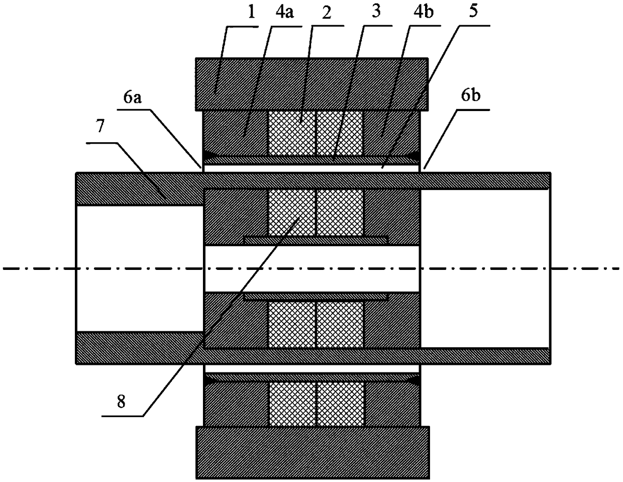
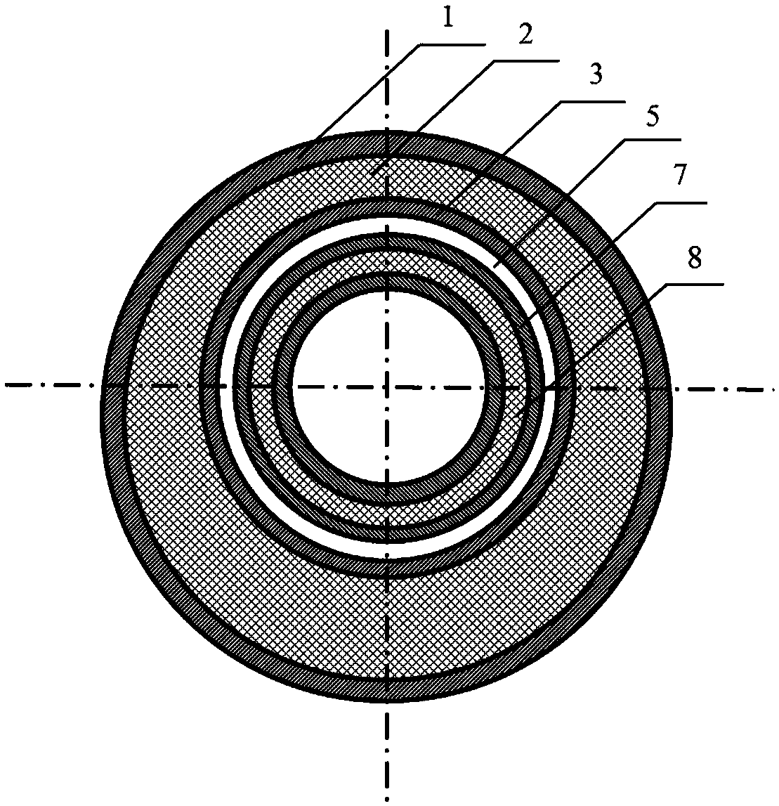
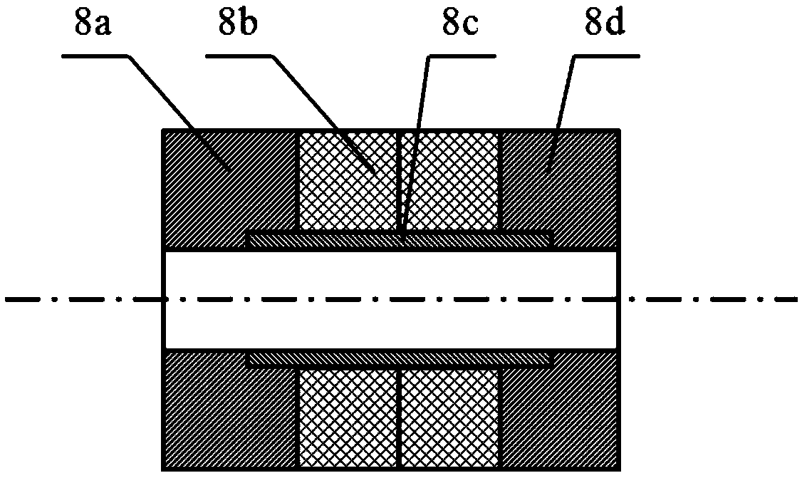
[0016] refer to figure 1 and figure 2 , a radial passive permanent magnet bearing structure with large damping and efficient cooling, including a stator permanent magnet 2 transitionally fitted with a stator frame 1, a sliding bearing 3 is arranged in the cavity of the stator permanent magnet 2, and the outer side of the sliding bearing 3 is connected to the stator permanent magnet 2 Adopt clearance fit, the two sides of the stator permanent magnet 2 are respectively bonded with the left plug 4a of the stator permanent magnet and the right plug 4b of the stator permanent magnet, and a stator-rotor gap 5 is provided between the inner side of the sliding bearing 3 and the outer side of the rotor sleeve 7 , there are oil inlet 6a and oil outlet 6b on both sides of the stator-rotor gap 5, lubricating oil enters the stator-rotor gap 5 from the oil inlet 6a, and ...


PUM


Abstract

The invention provides a large-damping efficiently-cooling radial passive permanent magnet bearing structure, comprising a stator permanent magnet which is in transition fit with a stator frame. A sliding bearing is arranged in the cavity of the stator permanent magnet; the outer side of the sliding bearing and the stator permanent magnet are in clearance fit; two sides of the stator permanent magnet are respectively bonded with a left plug and a right plug of the stator permanent magnet; a stator-rotor clearance is arranged between the inner side of the sliding bearing and the outer side of arotor sleeve; two sides of the stator-rotor clearance are respectively provided with an oil inlet and an oil outlet; a rotor permanent magnet assembly is installed on the inner side of the rotor sleeve in the manner of interference fit; the sliding bearing is built in the cavity of a radial passive permanent magnet bearing; and the gap between the sliding bearing and the rotor sleeve is filled with lubricating oil. The large-damping efficiently-cooling radial passive permanent magnet bearing structure of the invention effectively cools the bearing and a rotor, improves the rotation speed of the rotor, and enhances the stability of a bearing-rotor system at high a speed.

Description

technical field [0001] The invention relates to the technical field of passive permanent magnetic bearings, in particular to a radial passive permanent magnetic bearing structure with large damping and efficient cooling. Background technique [0002] In order to realize the stable suspension of the rotor, the traditional permanent magnetic bias active magnetic bearing needs to detect the position of the suspended rotor and actively control it by the control system; this kind of bearing does not have mechanical contact, so it has no friction, no wear and no lubrication. characteristics, but it requires a complex control system, so there are problems such as low reliability, high power consumption, and large volume. Although radial passive permanent magnetic bearings get rid of the dependence on the control system, the bearings have low stiffness and low damping and are only suitable for low speeds. In order to increase the speed of the rotor, a permanent magnet-hydrodynamic ...

Claims


Application Information

Patent Timeline
IPC IPC(8): F16C32/04F16C37/00
Inventor 程文杰邓志凯
Owner XIAN UNIV OF SCI & TECH
Learn More